
State what the light must enable
Record the area and task, the intended viewing direction and the relevant operating conditions. Coordinate with neighbouring properties and other site uses. NPSA’s security lighting guidance provides a security-specific reference; it is not a universal lux prescription for every fence.
Keep the agreed performance criteria with the lighting design. A luminaire’s power rating alone does not describe the illumination or useful image quality at the boundary.
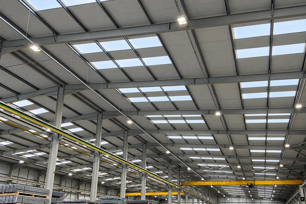
Treat the mounting as a structural addition
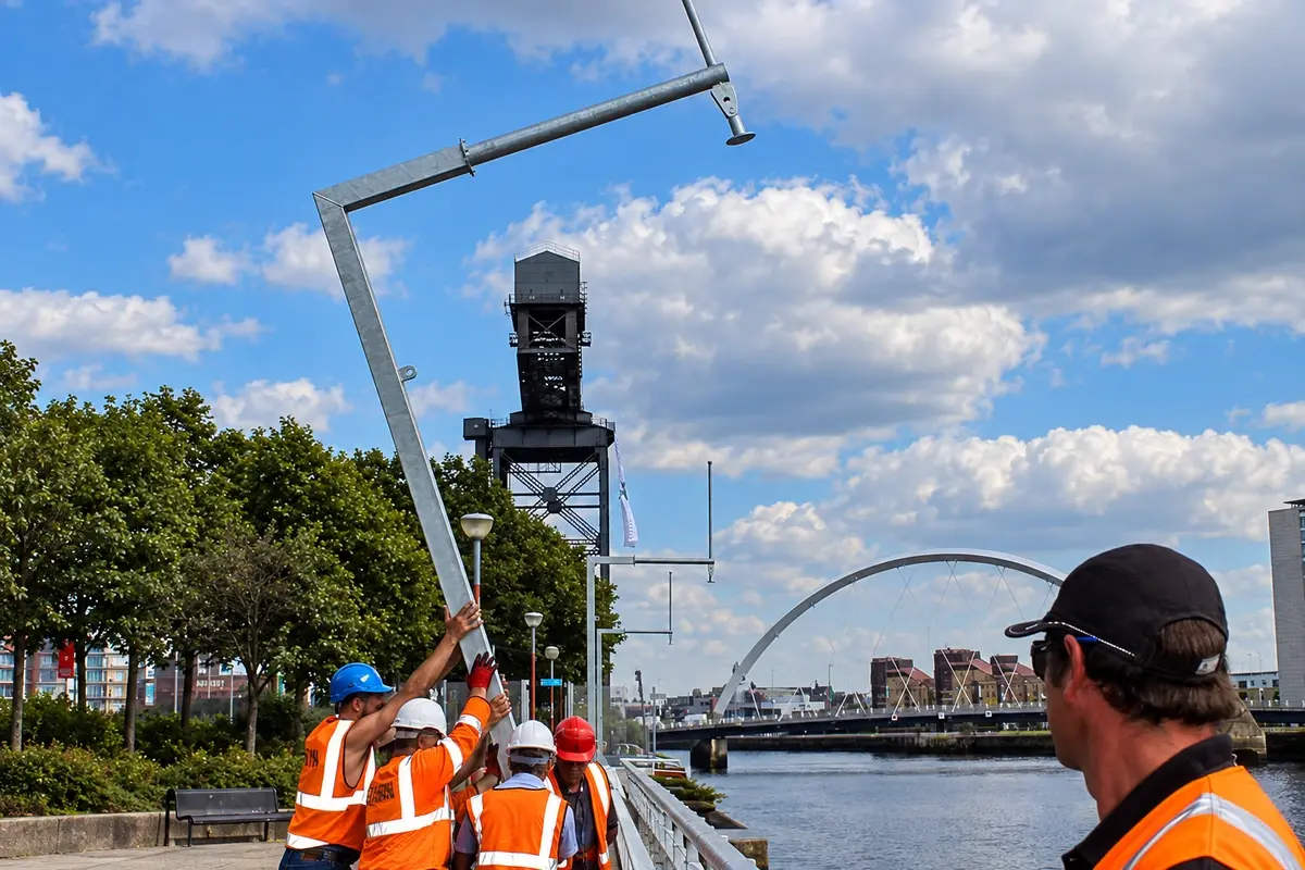
Identify the luminaire, bracket, attachment height, offset and relevant loads. Have the fence designer assess the proposed arrangement, including the supporting post and foundation. If the fence is unsuitable, a separately designed support may be needed.
Do not drill a post to fit a bracket without reviewing the detail and its protective finish. Record cable routing and any required electrical protection through the responsible specialist.
Read the measurements individually
Assume five illustrative readings at specified test locations are 18, 12, 9, 11 and 15 lx. Their arithmetic mean is 13 lx, while the minimum is 9 lx. The minimum-to-average ratio is approximately 0.69.
These are example measurements, not target values. Whether they meet a requirement depends on the applicable criteria, measurement plane, location and operating state. An acceptable average cannot prove that every location satisfies a minimum requirement.
| Record with the readings | Reason |
|---|---|
| Measuring points and plane | Allows the check to be repeated |
| Instrument and relevant status | Supports confidence in the measurements |
| Lighting state and conditions | Identifies what was actually tested |
| Fence and screen arrangement | Connects results to the installed geometry |
| Camera or observation task | Keeps the test related to its purpose |
Check the view as well as the numbers
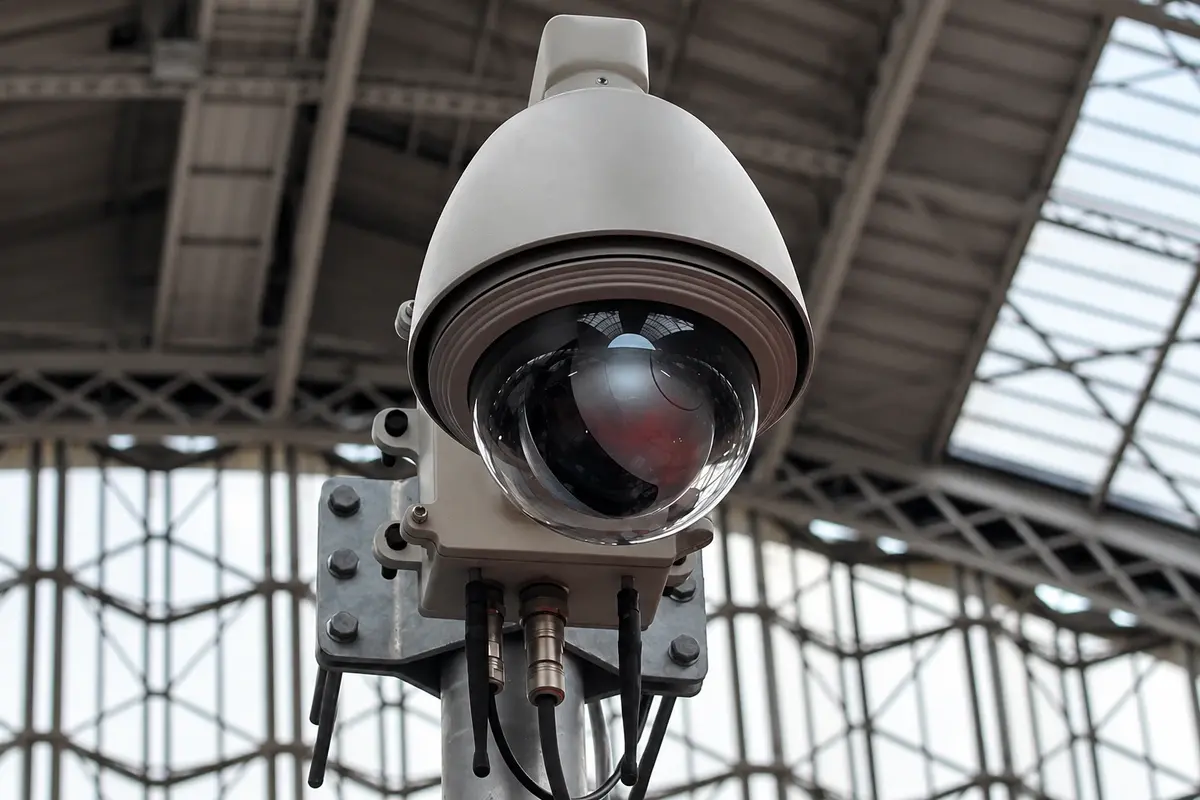
Review the intended camera or human view under the agreed night-time conditions. Mesh, posts, glare and shadows can affect the result. Adding lighting behind a screen may not illuminate the surface or subject that needs to be seen.
Have the relevant specialist evaluate the actual operating task. Do not claim a detection or identification distance from lux readings alone.
Preserve the result through maintenance
Record the accepted luminaire and bracket arrangement, aiming information where appropriate, and maintenance access. Reassess affected areas when screening, vegetation, camera positions or fittings change.
The finished package should connect the measured result to a defined physical installation. That makes later faults and upgrades easier to review than a purchase order containing only a luminaire quantity and a fence length.