
Read the required duty first
Identify whether the project needs boundary control, pedestrian guidance, vehicle restraint or a combination. Ask the responsible designer to define the required performance and the relevant assessment route.
NPSA’s vehicle mitigation resources distinguish specialist barrier evidence. A security barrier test is also not automatically interchangeable with every road-safety or car-park restraint requirement.
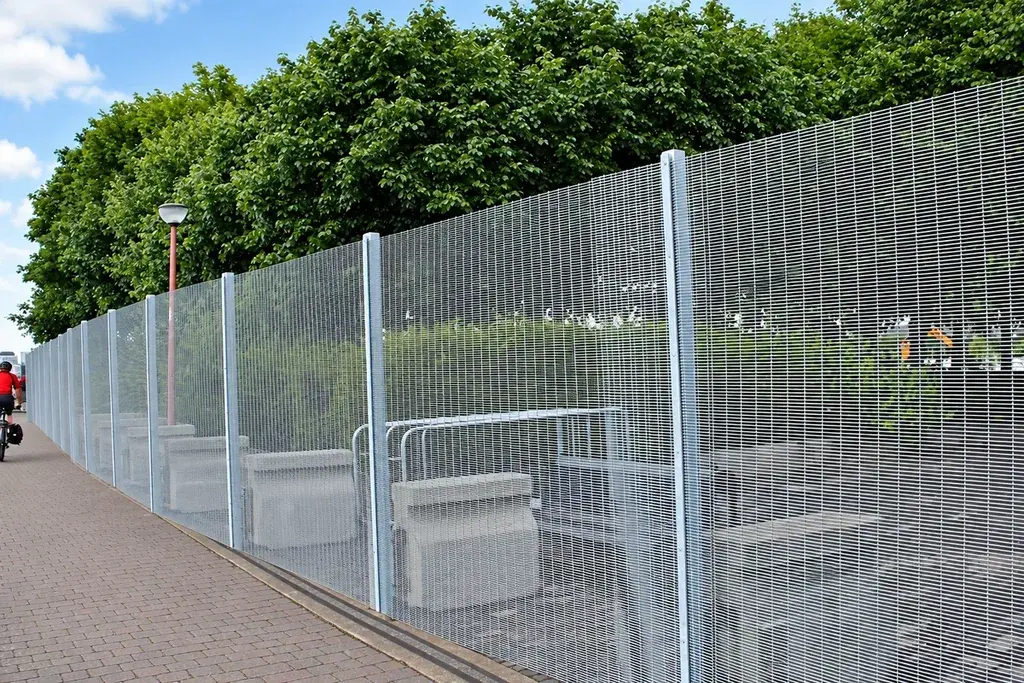
Use energy to understand scale, not to award a rating
The kinetic energy relationship is E = ½mv², using mass in kilograms and speed in metres per second. For an illustrative 1,500 kg vehicle:
| Speed | Converted speed | Approximate kinetic energy |
|---|---|---|
| 10 km/h | 2.778 m/s | 5.79 kJ |
| 20 km/h | 5.556 m/s | 23.15 kJ |
Doubling speed gives four times the kinetic energy in this simplified calculation. The numbers are explanatory, not suggested design scenarios or evidence that a particular fence can withstand either event.
Barrier behaviour also depends on the vehicle, impact conditions, assembly, foundations and other factors addressed by the relevant assessment. Matching a headline energy value cannot establish equivalent tested performance.
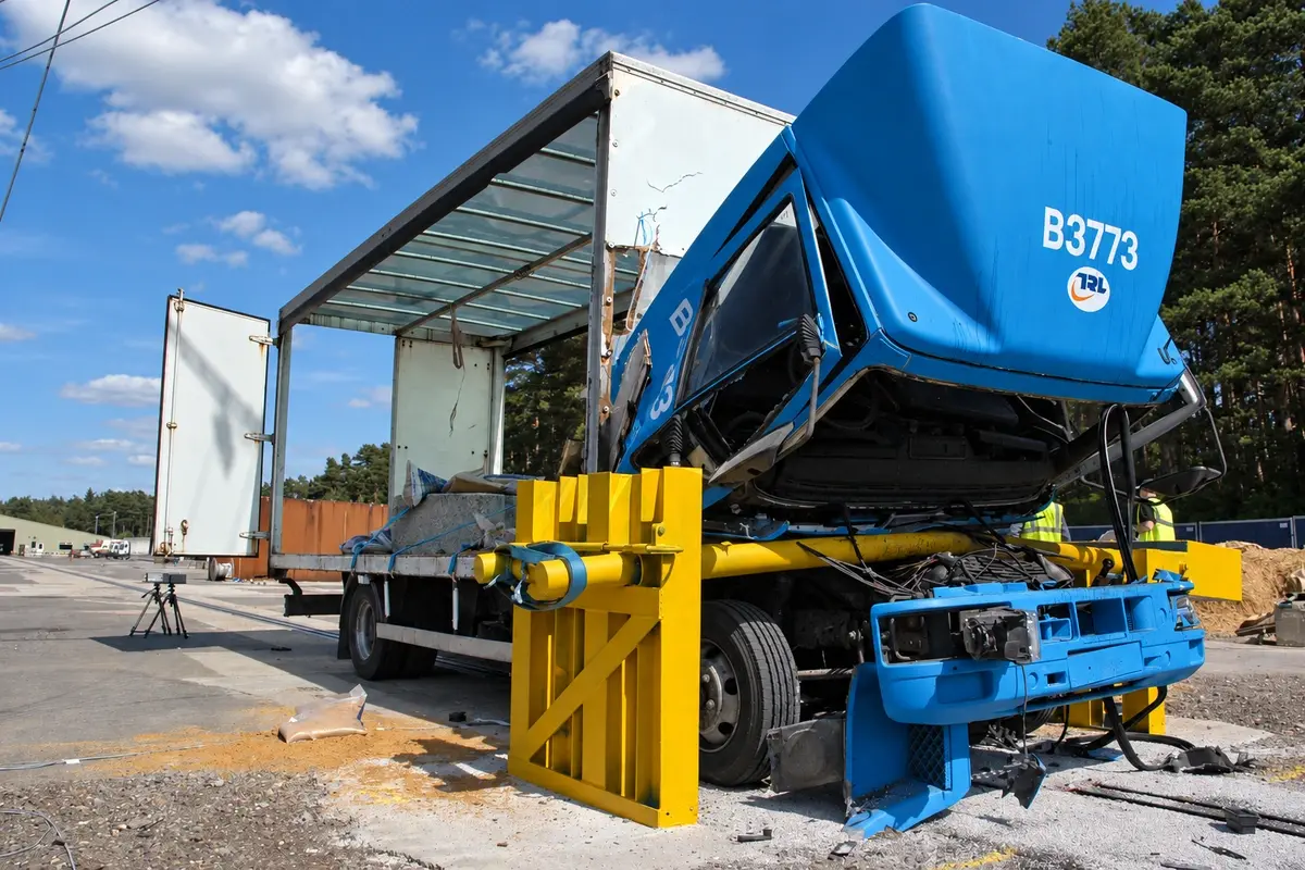
Match the evidence to the installed arrangement
Check the exact product, configuration, test reference and stated results. Identify the foundation or support arrangement associated with the evidence and compare it with the proposed site installation.
If a different slab, anchor arrangement, spacing or component is proposed, have the change reviewed by the responsible specialist. A test report for one arrangement should not be presented as covering an unassessed substitute.
Coordinate the neighbouring fence
Record the relationship between the barrier and the fence, including any space required by the barrier design and maintenance procedure. Nearby posts, gates, kerbs and equipment may affect the complete arrangement and should be included in the coordinated layout.
Do not use the fence as an attachment point for a restraint system unless that interface is part of the accepted design. Similarly, do not assume a barrier foundation can accept additional fence loads without review.
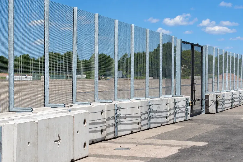
Make the quotation and handover unambiguous
Use separate line items for the boundary fence and the specified vehicle protection. Identify who supplies the relevant design, installation checks and operating or inspection information. Describe unprovided work clearly enough for the project team to assign it.
At handover, retain location-based asset records and the accepted evidence. Following an impact, use the required competent inspection process; visible uprightness alone is not proof that the system retains its intended performance.
The car park planning article applies this distinction to bay ends, pedestrian routes and access areas without treating every boundary as the same duty.