
By FencingWise Editorial Team · Updated 17 September 2026.
Define the surface from which clearance is measured
The reference should be the finished, maintainable surface below the panel. Loose vegetation, stored soil and temporary paving are unreliable references. Where the fence crosses a swale, kerb or retaining edge, describe the surface separately.
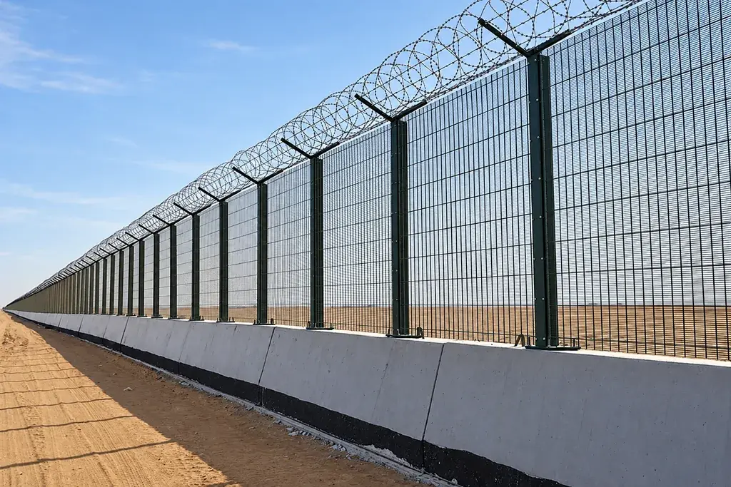
Use a vertical gap measurement unless the project detail specifies another convention. On sloping ground, the shortest distance perpendicular to the ground differs from the vertical distance. Mixing those readings makes two inspection sheets impossible to compare.
Record the approved maximum opening and its applicable detail. A number drawn from another project is not a general anti-burrow requirement. Sites differ in drainage, animal access, security objectives and available foundations.
Survey a bay at more than its ends
For an initial profile, measure at both posts and at intermediate positions. Add readings wherever the ground dips, changes material or shows erosion. A fixed spacing is a recording aid, not evidence that every smaller depression has been captured.
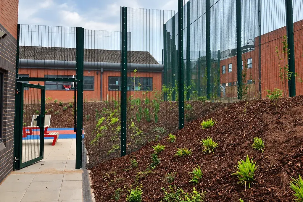
Consider an illustrative 2.5 m bay measured at five positions:
| Distance from left post | Vertical bottom gap |
|---|---|
| 0.000 m | 40 mm |
| 0.625 m | 55 mm |
| 1.250 m | 95 mm |
| 1.875 m | 60 mm |
| 2.500 m | 45 mm |
The average is 59 mm, but the controlling observed opening is 95 mm. If this fictional project permits a maximum of 60 mm, the midpoint fails by 35 mm, even though both ends comply. The 60 mm limit is an example assumption, not a universal security criterion.
Photograph the measuring rule against the opening and identify the bay. A close-up without a bay number cannot reliably support a later repair instruction.
Allow for the ground changing after installation
Suppose the panel remains fixed and the soil beneath it settles by 30 mm. A previous 45 mm opening becomes 75 mm. Similarly, erosion can reopen a gap after a cosmetic soil fill.
This is why the correction should address the cause. Loose topsoil placed below the panel may close the gap for a photograph but fail after rainfall or routine maintenance. A permanent detail needs to suit the local surface, drainage and maintenance equipment.
At a paved threshold, check the final surface level before manufacturing a special panel. At a drain, identify who maintains the channel and how access will remain possible after the boundary treatment is installed.
Compare closure methods by the problem they solve
| Site condition | Possible detail to investigate | Main interface to resolve |
|---|---|---|
| Gradual slope across several bays | Stepped, raked or shorter-bay arrangement | Panel geometry and post positions |
| Isolated depression | Designed infill or durable ground reconstruction | Fixing and finished surface |
| Persistent washout | Drainage correction with a compatible barrier | Water passage and erosion control |
| Required resistance below ground | Engineered buried or apron detail | Corrosion exposure, services and excavation |
| Gate threshold | Coordinated leaf and threshold design | Operating clearance throughout travel |
A strip fixed only to unsupported wire may not provide the intended load path. Show how an infill attaches to posts, frames or other approved supports. Avoid introducing sharp edges at a public-facing bottom line.
Buried metal changes the exposure conditions. A finish selected for above-ground atmospheric exposure should not automatically be assumed suitable for soil contact. Underground services must also be established before excavation.
Check the drainage opening as a separate boundary element
A culvert or channel can be much wider than the surrounding mesh apertures. Its detail should therefore be drawn explicitly, including removable sections and fixing access.
For a rectangular illustrative channel 600 mm wide × 300 mm high, the gross opening is 0.18 m². Adding bars reduces the unobstructed flow area, but hydraulic capacity cannot be calculated by subtracting bar area alone. Debris blockage, water level and flow conditions also matter.
Use that gross dimension to start coordination with the drainage designer. The security detail and the hydraulic detail need to describe the same opening. A grating that is difficult to remove may also be difficult to clean.
Verify the correction where it was originally measured
After work, revisit the same positions and use the same datum. Record the maximum opening, not only a favourable average. Check both sides of an added closure and any new gap between it and the original panel.
The completion record should contain the original measurements, approved remedy, after-work readings and photographs. If settlement or erosion caused the defect, identify the inspection event that will confirm the remedy remains effective, such as a subsequent rainfall inspection.
For changes affecting several bays, use the stepped-versus-raked calculation guide alongside this local gap survey. One establishes the overall geometry; the other finds the openings that a smooth profile can miss.