
By FencingWise Editorial Team · Updated 17 September 2026.
Do not assume a rigid welded panel can be forced into a raking shape on site. The construction must provide the required geometry.
Distinguish stepping from following the slope
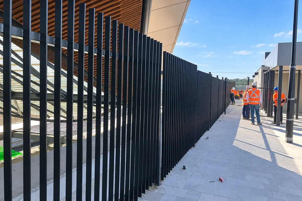
With stepped fencing, each panel remains in its specified level orientation and successive panels sit at different elevations. Their connections meet a post at different heights.
A raked arrangement follows the slope while maintaining the geometry its system is designed to provide. Some railing systems allow controlled movement at their connections; welded mesh may require a manufactured sloping panel or another approved detail. Rotating a standard rectangle is not necessarily equivalent, because its side edges and connections also rotate.
Slope connections depend on panel type and step size. Confirm the components, dimensions and permitted adjustment for the selected system; details from another system may not apply.
Calculate the rise within one bay
Assume a fictional uniform slope with a horizontal bay length of 2,500 mm and a gradient of 8%.
The ground rises:
2,500 × 0.08 = 200 mm per bay.
Across four such bays, the horizontal distance is 10,000 mm and the total rise is 800 mm.
This calculation describes the site geometry. It does not approve 2.5 m support spacing, a 200 mm step or any particular panel design.
Measure actual ground changes along the run. A uniform gradient calculation will not capture a local dip, kerb or drainage channel between the support positions.
See what stepping does to the bottom gap
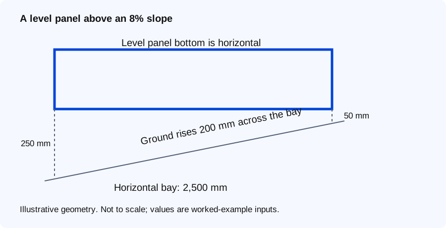
Open the full-size dimension diagram.
In the same example, suppose a level panel is positioned with its bottom 50 mm above the ground at the higher end. At the lower end, the ground is 200 mm lower, so the gap becomes:
50 + 200 = 250 mm.
The panel still has the same nominal height, but the gap varies from 50 to 250 mm. Whether that is acceptable depends on the boundary's function and project requirements.
Now consider a hypothetical redesign dividing that horizontal distance into two 1,250 mm bays. Each bay rises 1,250 × 0.08 = 100 mm. With the same 50 mm high-end clearance assumption, the low-end gap is 150 mm.
Shorter steps reduce the geometric gap in this example, but they add supports and alter panels and fixings. They are a design option to assess, not an automatic field correction.
Keep horizontal distance and sloping length separate
A slope-following member spanning 2,500 mm horizontally with a 200 mm rise has a straight slope length of:
√(2,500² + 200²) = 2,507.99 mm.
The approximate 8 mm difference may look small, but it matters when matching defined interfaces. A drawing must state whether a width is measured horizontally, along an inclined edge or between particular fixing points.
This calculation alone cannot size a raked panel. Vertical edges, wire angles, frame geometry and the connection method remain part of the design. Use the geometry to identify the question, then obtain the appropriate panel detail.
Map the post and fixing positions
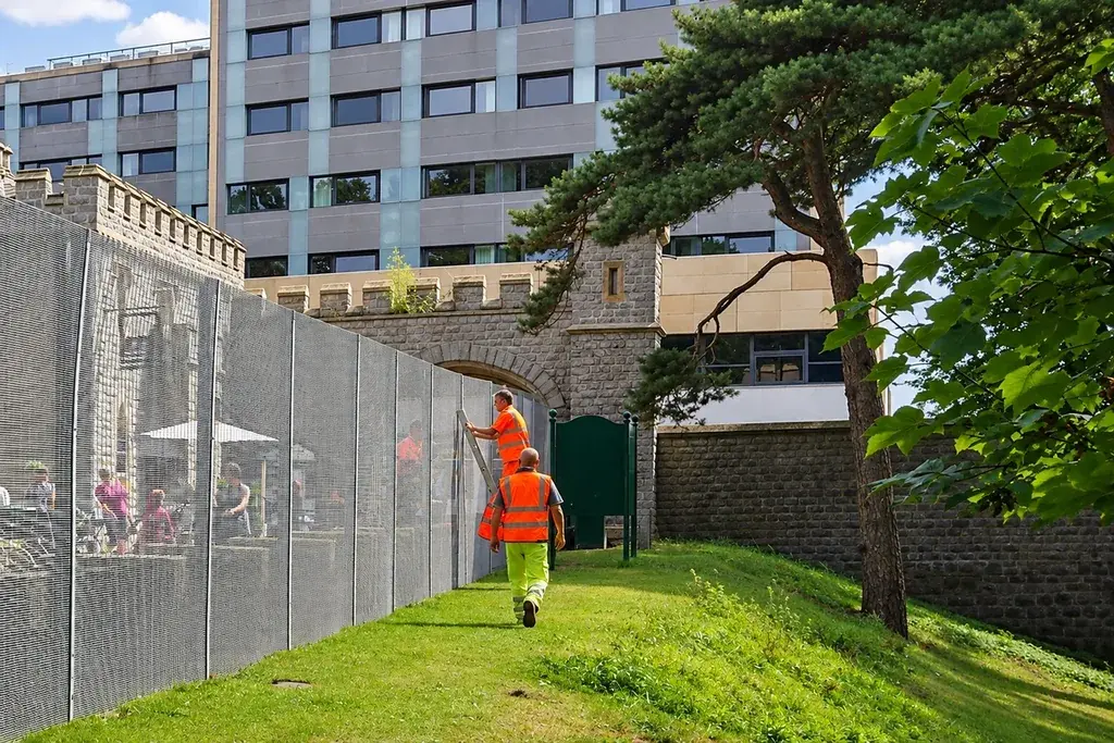
On a stepped run, adjoining panel tops and bottoms reach the post at different levels. Record the absolute fixing elevations or dimensions from a defined post datum.
Check whether the post has the required length and approved fixing positions. A standard hole pattern may not accommodate an arbitrary step. Clamp bars may also need different lengths or separate arrangements for the two edges.
At a change from level ground to a slope, identify the transition as its own node. The same applies at a gate, retaining wall or corner. A drawing of only the repeated middle bays can miss the most difficult connection.
Choose the arrangement with a comparison table
| Project condition | Option to examine | Key check |
|---|---|---|
| Modest level changes and acceptable stepped appearance | Stepped standard panels | Bottom gaps and compatible fixing elevations |
| A tight ground-following requirement | Designed raked or specially manufactured arrangement | Panel geometry, connection capability and performance |
| Irregular ground with local depressions | More detailed survey and local transition design | Gaps between measured main points |
| Existing fixed posts | Compatible replacement detail | Available heights, hole pattern and remaining condition |
The important selection question is which arrangement meets the required ground relationship with a defined, inspectable connection. Neither appearance nor panel price should hide an unresolved gap.
Review the proposal in a fixed sequence
First confirm the survey and proposed finished levels. Next plot panel bottoms and tops in elevation, then mark gaps at the locations where they are largest. Add posts, fixing positions and transitions.
After that, count standard and non-standard components separately. Check whether any proposed trimming changes the panel edge or coating, and obtain the required approved detail before treating it as part of the installation.
Finally, review gates against the ground throughout their movement. A stepped fixed fence beside an entrance does not solve a swing leaf that meets rising paving.
Carry the resolved geometry into the order
The order should identify each panel arrangement, its drawing reference and the post/connection schedule. Include orientation where a sloping or asymmetric panel can be fitted only one way.
Use the survey method to collect the levels and the quantity takeoff method to count the resulting components. The aim is to turn the slope into specified parts before installation, rather than leave the installer to cut, rotate or raise panels until they appear to fit.