
By FencingWise Editorial Team · Updated 17 September 2026.
The useful output is a marked plan, a level record and identifiable photographs that a designer or supplier can read together.
Establish a start point and direction
Choose a repeatable reference point, mark it on the plan and define the direction of increasing distance along the fence line. Distances along the route are often recorded as chainage.
Separate measured conditions from the approved legal boundary. A physical fence, kerb or wall does not by itself establish land ownership. Use the project's authorised boundary information for the intended line.
Give each corner, gate and termination a reference. A note saying “gate near warehouse” is less useful than “G-02 between points S-12 and S-13”. The reference should appear on the plan, photograph and gate schedule.
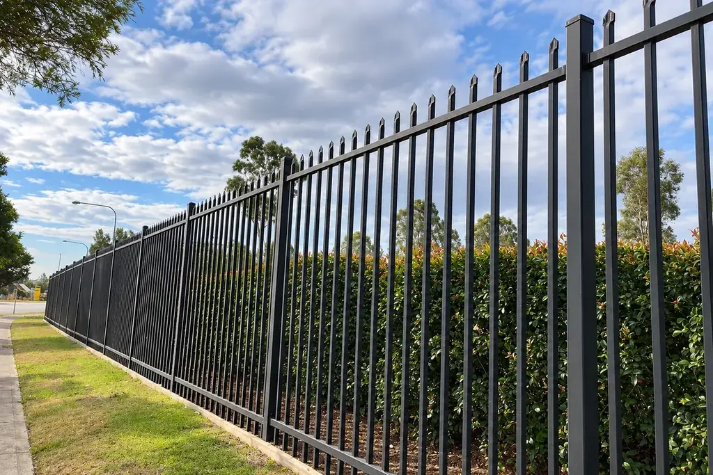
Measure each segment between defined points
Record whether a length is horizontal plan distance, distance along sloping ground, post-centre spacing or clear space between fixed faces. These values cannot be exchanged without a geometric check.
Break the route at changes in direction and other constraints. Record the corner angle or coordinates rather than assuming every turn is 90°. Note walls, drainage features, existing supports and obstructions that affect the line.
Where a measuring tool cannot reach the intended reference, record the limitation. Do not enter an estimated dimension as though it were a direct measurement.
Use a level table to make slopes visible
Consider this fictional survey along a 10 m horizontal run:
| Chainage | Recorded level relative to the chosen datum |
|---|---|
| 0 m | 100.00 m |
| 2.5 m | 100.20 m |
| 5.0 m | 100.40 m |
| 7.5 m | 100.60 m |
| 10.0 m | 100.80 m |
The rise is 100.80 − 100.00 = 0.80 m over 10.00 m horizontally. The gradient is:
0.80 ÷ 10.00 × 100 = 8%.
For this straight, uniform example, the slope length is:
√(10² + 0.8²) = 10.032 m, approximately.
The horizontal and sloping distances differ by about 32 mm. Neither should be silently substituted for a connection or panel dimension.
These figures demonstrate a survey record and calculation. They are not an instruction to use 2.5 m post spacing or a permitted slope for a particular fence.
Record local changes between the main points
Uniform tables can conceal a dip, raised kerb or drainage channel between measured stations. Add measurements where the ground changes, particularly near gate travel and panel bottoms.
The survey should distinguish existing ground from proposed finished levels. A fence designed around today's surface may have different bottom gaps after paving or grading.
The stepped and raked comparison explains how levels affect panel arrangement. A supplier should receive the actual changes rather than only the total rise from one end of the site to the other.
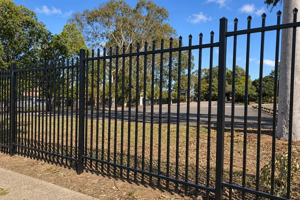
Survey gates as separate assemblies
At each opening, identify the required usable passage, fixed walls or posts, available swing or run-back space and finished ground along the entire travel route. Include nearby parking, equipment and pedestrian routes.
For a sliding gate, a clear entrance does not establish clear space beside the fence. For a swing gate, the ground under the closed leaf is only part of the relevant surface; the open arc also needs review.
Record both the required result and the measured constraints. Do not derive a new gate leaf width merely by measuring an old leaf whose hinges and clearances may differ.
Record ground and service constraints without guessing
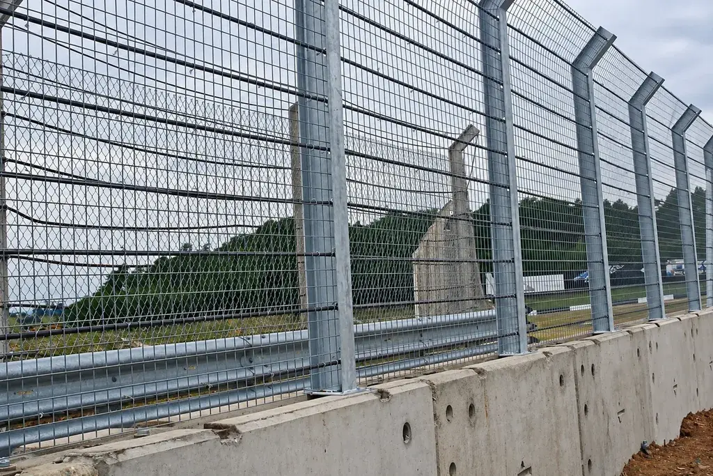
The proposed foundation locations need information about buried services, nearby structures, drainage and the available support. A photograph of concrete does not establish its thickness or suitability for anchors.
HSE's underground-services guidance separates planning, locating services and safe excavation. Existing drawings are part of that process; they are not permission to start digging at an assumed clear point.
The survey package should identify known information, investigation results and unresolved items for the responsible team. It should not invent embedment depths or foundation sizes to make the schedule appear complete.
Photograph measurements so they can be located later
Take an overview showing the reference point, a view along the run and close views of interfaces. Use filenames or captions that include the survey point or gate reference.
A practical sequence for one corner might include C-03 overview, C-03 angle/measurement and C-03 ground detail. The photographs then support the plan rather than becoming an unlabelled gallery.
Include a scale where it helps explain a detail, but retain the measured dimension in the record. Perspective and lens distortion make photographs unsuitable as the sole source of critical dimensions.
Issue a survey package that exposes unresolved decisions
Before issuing the package, check that run references, level points and gate IDs agree across documents. Reconcile segment lengths with the overall route and explain any difference in measurement basis.
List missing information with an owner and next action: for example, final paving level from the main contractor or existing slab information from the designer. Keep provisional quantities marked until those inputs are resolved.
FencingWise can use this material for the specification and component discussion. The final survey record should let another person locate every important dimension and understand what remains unknown, without needing to repeat the original site conversation.