
By FencingWise Editorial Team · Updated 17 September 2026.
Count the layout first, then derive the component schedule.
Split the route at gates and special nodes
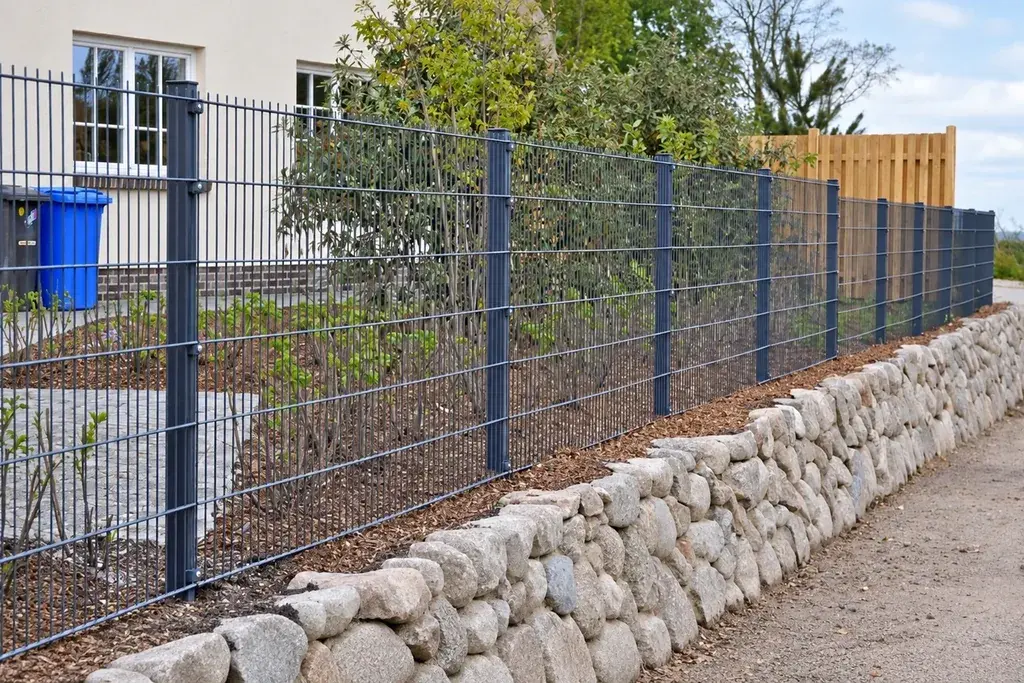
Give every continuous fixed-fence run a reference. Mark ends, corners, junctions, gates and wall returns. Identify whether the fixed fence connects to gate posts or ends on separate supports.
Use a single dimension convention within each calculation. A total outside-to-outside boundary length cannot be combined directly with gate clear opening and post-centre bay dimensions without including the missing post widths and offsets.
The panel and bay-width article explains that geometry. Resolve it before using a calculator to produce apparently precise quantities.
Define the worked example completely
Assume a fictional route from the first fixed-fence post centre to the last comprises:
- Fixed run A: 22.5 m, between its terminal post centres.
- A defined central zone: 5.0 m between the two nearest fixed-fence terminal centres.
- Fixed run B: 22.5 m, between its terminal post centres.
The total reference distance is 22.5 + 5.0 + 22.5 = 50.0 m.
Inside the central zone sits a gate with 4.0 m usable opening. A separately designed gate-and-return arrangement closes the full 5.0 m zone, including its two gate posts and fixed side interfaces. Its leaves, return components and hardware are purchased as one identified package; the two gate posts are counted separately below. Each fixed run has its own terminal beside that arrangement.
This explicit layout prevents the common error of subtracting a 4 m clear opening directly from a 50 m centre-based measurement.
Count standard and closing bays
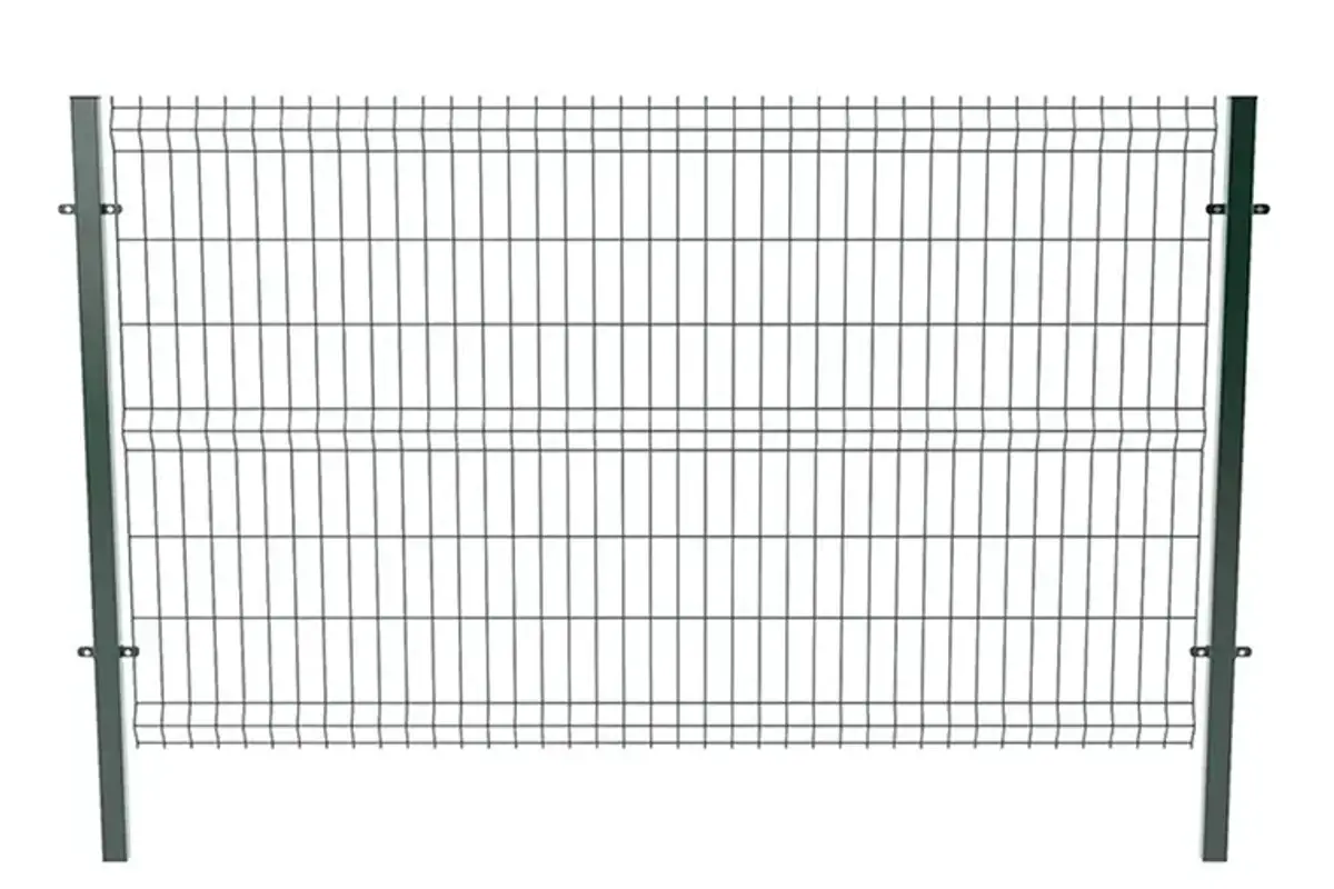
For illustration, suppose the approved fixed-fence system uses standard 2.4 m installed bays. Each 22.5 m run can contain:
9 × 2.4 = 21.6 m of standard bays.
The remaining installed bay is:
22.5 − 21.6 = 0.9 m.
Each run therefore has 9 standard bays and 1 designed closing bay, or ten panels. Across both runs:
| Panel type | Run A | Run B | Total |
|---|---|---|---|
| Standard | 9 | 9 | 18 |
| Closing | 1 | 1 | 2 |
| All panels | 10 | 10 | 20 |
The 0.9 m value is an installed bay dimension, not automatically the physical closing-panel width. Derive that width from the connection detail. The example does not authorise cutting a standard panel to 900 mm.
Count posts from the nodes
An open run of ten connected bays uses ten plus one = eleven supports, under this example's shared intermediate-post arrangement.
For two separate runs, the fixed-fence post count is:
11 + 11 = 22.
Each run has two terminal posts and nine intermediate posts, giving 4 fixed-fence terminals and 18 line posts overall. Add the two separately defined gate posts:
22 + 2 = 24 total posts.
The central-zone order line is one gate-leaf, fixed-return and hardware package, excluding the two gate posts already counted. Its approved drawing must establish the 4.0 m usable opening within the 5.0 m zone. The twenty fixed-run panels do not include those return components.
If the design instead connected the fence directly to gate posts, the schedule would be different. Do not subtract two posts from the example without also changing and approving the interface details.
Add fixings from the actual edge arrangements
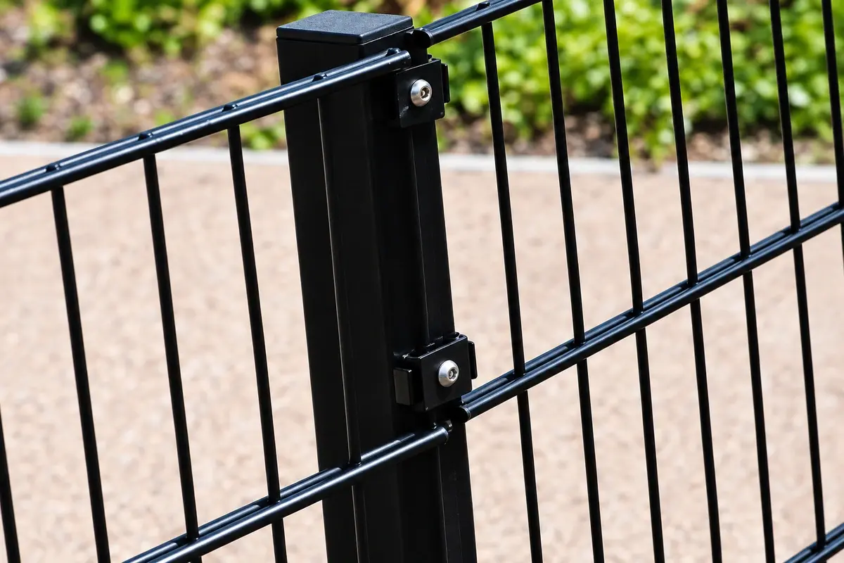
Assume four independent complete fixing sets per vertical panel edge for this counting exercise. Twenty panels have forty edges:
20 × 2 × 4 = 160 fixing sets.
This is not a recommended fixing spacing. It is a stated assumption used to demonstrate the method.
If the two closing panels require a different fixing arrangement, replace their contribution with that actual detail. For example, the standard panels contribute 18 × 2 × 4 = 144 sets. The closing-panel hardware then becomes a separately counted line, rather than being hidden in a general allowance.
Caps, gate hardware and any base connections need their own component references. Establish whether those items are included in a quoted assembly before adding them separately.
Reconcile dimensions and quantities independently
Use two checks. First, add the bay dimensions within each run: 9 × 2.4 + 0.9 = 22.5 m. Then count the support nodes on the drawing.
Do not use the calculated panel quantity as proof of the post quantity. A corner with separate supports, a branch or a shared gate post can change the node count without changing the number of panels.
For more complex layouts, label each node once and classify its duty. The end, corner and line-post guide shows how a shared corner can otherwise be counted twice.
Keep allowances visible
Suppose the buyer adds one standard replacement panel and eight complete spare fixing sets. The order would contain 19 standard panels, 2 closing panels and 168 fixing sets, assuming the example's unchanged installation detail.
The installation requirement remains 18 standard panels, two closing panels and 160 sets. Record the additions as spares, with the appropriate storage and packing references.
A spare standard panel does not replace a missing closing-panel design. Likewise, extra line-post clips cannot solve an uncounted gate connection.
Issue the schedule with its assumptions
Each line should identify the item, quantity, unit, drawing reference and included components. Attach the layout revision that generated it and list any unresolved interfaces explicitly.
If the gate zone or run length changes, recalculate the affected bays, support nodes and fittings together. Updating only the panel total leaves the schedule internally inconsistent.
The completed takeoff should be reproducible by another person from the same drawing. That is a better measure of accuracy than a long spreadsheet containing numbers with no visible dimensional basis.