
By FencingWise Editorial Team · Updated 17 September 2026.
Position describes the connection duty
| Position | What changes at the node |
|---|---|
| Line | Two neighbouring bays connect along the run |
| End | The fence terminates, usually with a connection on one side |
| Corner | The adjoining bays meet at a different angle |
| Junction | More than two runs meet and need a specific detail |
| Gate position | Moving-leaf or catch hardware adds a separate duty |
Some systems use the same basic post section at several positions with different fittings. Other systems require different posts. The position name alone does not establish which parts are interchangeable.

Count one continuous run from its nodes
For a simple open chain of connected panels, with no gate, branch or separate support at a corner, N bays use N + 1 posts. Each additional bay shares one existing post and adds one new post.
Consider an illustrative L-shaped fence with three bays before a corner and two after it. There are five bays and six posts:
- Two end posts.
- One shared corner post.
- Three line posts.
Counting each leg separately gives four posts for the first leg and three for the second. The apparent total of seven counts the same corner twice. Subtracting that shared node gives six.
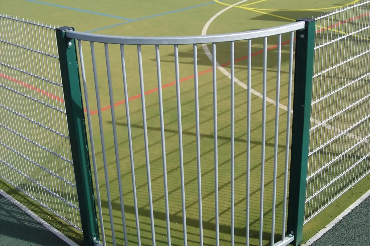
This is a counting example, not a recommendation to use one corner post in every system. The approved connection may require a different arrangement.
Gate openings interrupt the simple rule
A gate introduces its own supports and connection details. The adjacent fence might return to a gate post, or it might end on a separate post beside it. Those layouts produce different quantities.
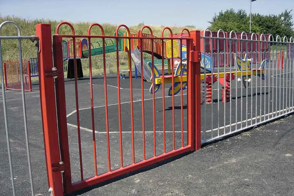
A closed loop also differs from an open chain, and a T-junction introduces another connection direction. Draw and label the nodes rather than applying the open-run formula to the whole site.
Angles and ground levels affect the fittings
A corner that appears square on a sketch may have a different measured angle. A bracket with a fixed angle may not accommodate it. Changes in level can also move the panel connections up or down the post.
Mark each non-standard node with its angle, adjoining panel references and relative levels. The clamp and bracket guide helps identify what must match.
Carry node references into the parts list
A schedule can use references such as E1 for an end, C1 for a corner and L1 for a repeated line detail. Keep those references consistent between the layout, post order and fittings list.
The next step is to count the hardware at each node. The accessories BOM example shows why panel edges and post positions are related but not always counted in the same way.