
By FencingWise Editorial Team · Updated 17 September 2026.
Start with a horizontal connection detail
For a panel sitting between two equal-width posts, each post contributes half its width to the centre-to-centre dimension. Add the panel width and the fixing clearance at each side.
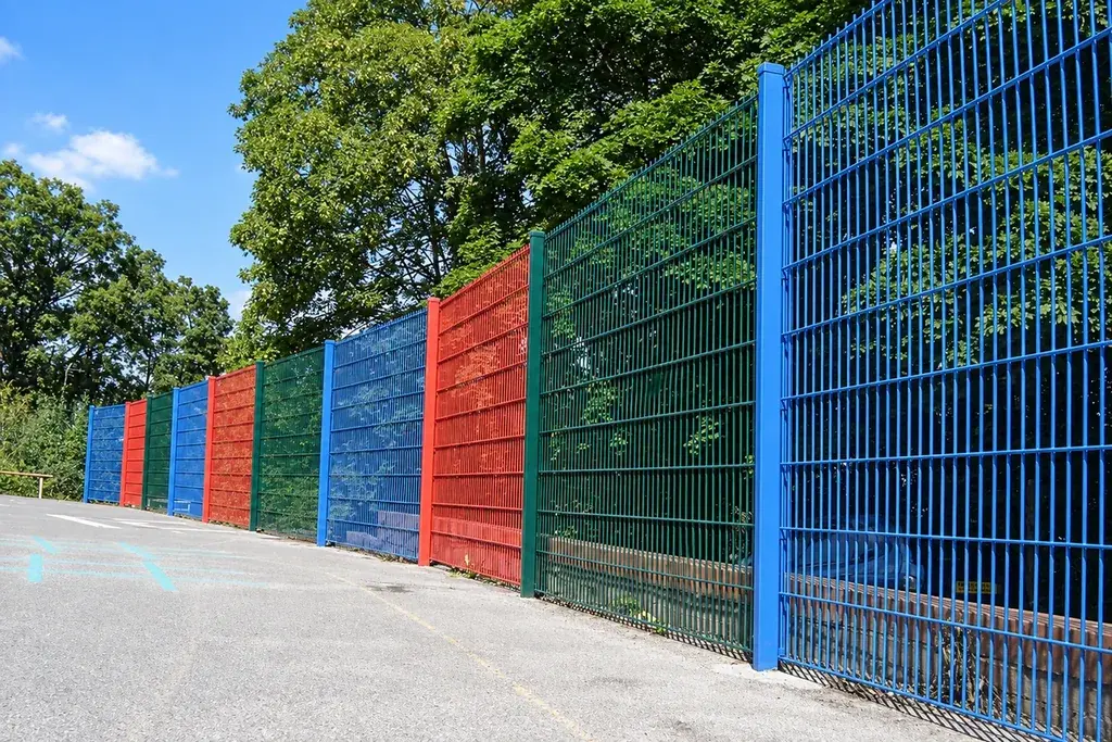
For an overlapping face-mounted panel, the relationship is different: the panel may extend across part of a post rather than stop between the posts. The actual node drawing determines the formula.
Worked example: a panel between posts
Assume a straight, level run with the following illustrative connection:
| Dimension | Assumed value |
|---|---|
| Panel width | 2,410 mm |
| Clearance from panel edge to post face, each side | 15 mm |
| Post width along the fence line | 60 mm |
The bay dimension is:
2,410 + 15 + 15 + 30 + 30 = 2,500 mm between post centres.
Ten identical bays therefore span 25,000 mm between the first and last post centres, using ten panels and eleven posts. The outside-to-outside length across the end posts is 25,060 mm.

These dimensions demonstrate the geometry only. They are not a product specification, installation clearance or permitted structural spacing.
State where the fence length begins and ends
“25 metres of fence” might mean a boundary survey distance, an outside-post dimension or a centre-to-centre setting-out length. Those are different references. A gate opening within the run changes the panel length again.
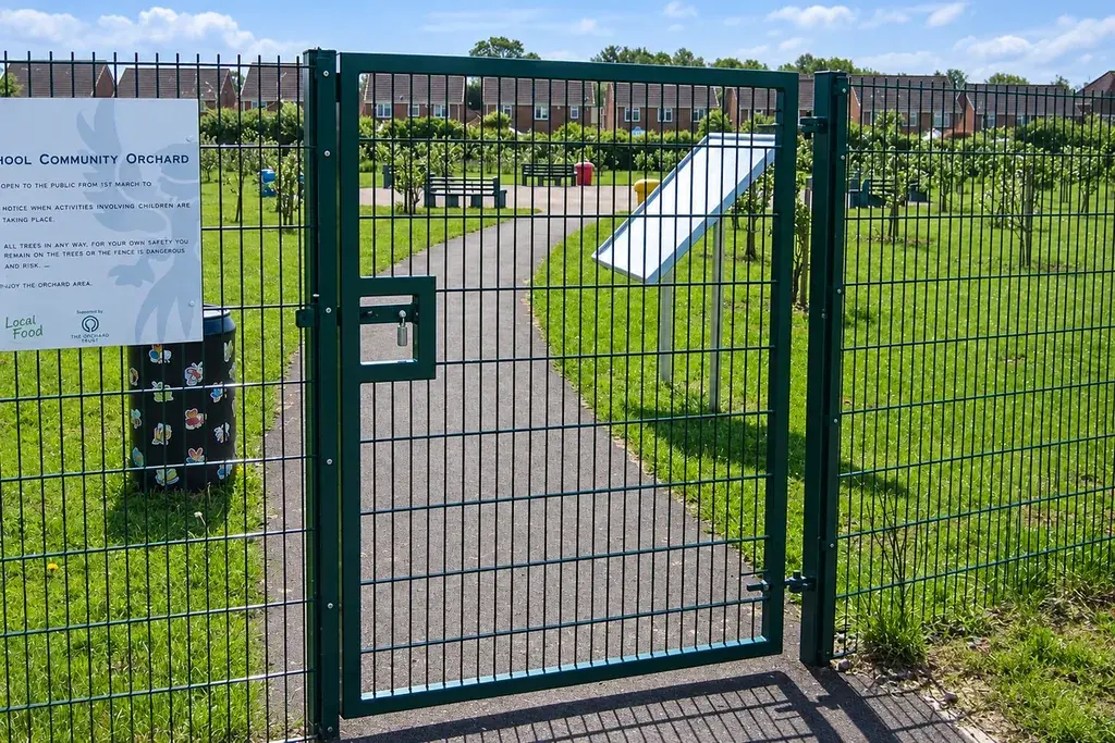
In the example, dividing 25 m by the 2.410 m panel width suggests 10.37 panels. That result is not the bay count because it ignores the posts and fixing spaces. Use the installed bay dimension for layout, then derive the material list.
Deal with the closing bay deliberately
A remaining short bay may need a different panel width or an approved closing detail. Cutting a standard panel can alter edge wires, fixing positions and coating protection, so it should not be the unrecorded default.
Corners and changes in level should be separated from the straight-run calculation. The end, corner and line post guide shows how those positions affect counting.
The handover from geometry to specification
Once the layout dimensions are established, the responsible designer confirms the permitted support spacing and foundation arrangement for the site. Geometric fit alone does not establish structural suitability.
Keep the bay drawing with the panel reference and post specification. It is the most useful record when an installer, buyer or future maintenance team needs to understand why that panel fits those post positions.