
By FencingWise Editorial Team · Updated 17 September 2026.
State what the camera must show
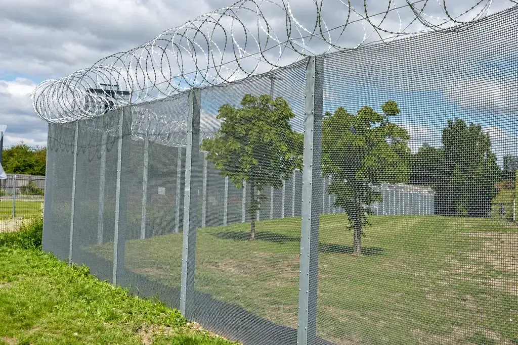
A camera used to verify a perimeter alarm needs a different view from one used to identify a person at an entrance. Write the task for each camera position before selecting a lens or drawing coverage cones.
NPSA's CCTV guidance distinguishes uses including alarm verification, tracking and recorded evidence. It also describes overlapping fixed perimeter views. These are useful planning principles; the final image requirement still belongs to the specific site.
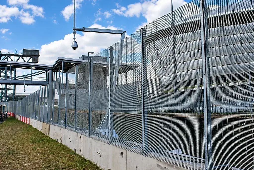
For each view, identify the target area, the smallest relevant event and the conditions in which it must be visible. Include the lower fence edge, gate recesses and corners if those locations form part of the required surveillance task.
Use pixel calculations to expose over-wide views
An elementary calculation helps compare candidate layouts:
Horizontal pixel density = horizontal image pixels ÷ scene width at the target plane.
Assume a camera records 1,920 horizontal pixels. If its view at the fence covers 24 m, the nominal density is 80 pixels/m. Narrowing that view to 12 m gives 160 pixels/m.
For an illustrative target 0.50 m wide, those densities correspond to approximately 40 pixels and 80 pixels across the target. This is a sampling calculation, not a declaration that either image meets a recognition or identification standard. Compression, motion, focus, lighting and obstruction can all make the real image less useful.
Calculate at the relevant distance. A density quoted for a near gate cannot describe the far end of the same view. Where perspective changes markedly, record several target planes.
Understand why mesh angle matters
Take a hypothetical flat mesh with pitches of 76.2 mm and 12.7 mm, both measured between wire centres, and finished wire diameter 4 mm. Ignoring welded overlaps and perspective, its approximate normal-view open fraction is:
[(76.2 − 4) ÷ 76.2] × [(12.7 − 4) ÷ 12.7] = 0.649, or about 64.9%.
This geometric estimate does not mean that 64.9% of every camera image remains usable. A post can fully hide a person at one location. Two mesh layers can overlap differently as the viewing angle changes. A wire close to the lens can blur across a much larger part of the image than its physical width suggests.
Consequently, do not convert the open fraction into an assumed reduction in pixel density or use it as a visibility acceptance test.
Set up a repeatable on-site trial
Use the intended mesh, finish and relevant post detail. Mount the camera at the proposed height and offset, or reproduce these as closely as practical in a controlled trial.
- Mark the near, middle and far target positions on the plan.
- Include a position directly behind a post and another behind a panel overlap.
- Use the proposed lens, recording resolution and normal compression settings.
- Record a person or suitable test target moving across each position.
- Repeat the exercise in daylight and under the intended night lighting or infrared mode.
- Export recordings from the system that operators will actually use.
- Record any location where the specified task cannot be completed.
The operator should assess the recorded result, not just a high-quality live image displayed during setup. Document the direction of travel and whether clothing, shadows or reflections make the target harder to separate from the background.
Separate obstruction from image-setting problems
| Observed result | Likely investigation | Useful next trial |
|---|---|---|
| Target disappears behind a post | Physical line of sight | Move viewpoint or add overlapping coverage |
| Near mesh appears bright at night | Illumination and reflection geometry | Change light position or camera offset |
| Far target occupies too few pixels | Lens and coverage width | Narrow the view or split the coverage |
| Stationary detail is clear but movement blurs | Exposure, lighting and recording settings | Repeat a moving-target test |
| Gate leaf blocks the view when open | Operating geometry | Test the gate in every normal position |
Treat these as diagnostic directions rather than guaranteed fixes. Moving a camera may improve one location and create another blind area. Repeat the same marked test route after each change.
Include maintenance access in the layout
Vegetation, dirt on the lens and new stored materials can invalidate a successful initial test. Save the test positions and representative images with the handover documents. A later inspection can then reproduce the comparison instead of relying on the statement that “the camera still works”.
Keep access to cameras compatible with the fence's security function. Supports, ladders and lighting columns should be reviewed as part of the anti-climb assessment.
The completed CCTV and fence coordination drawing should show camera positions, the tested view limits, post obstructions and the gate positions used during assessment. This gives the installer a measurable arrangement and gives the site operator a baseline for future changes.