
By FencingWise Editorial Team · Updated 17 September 2026.
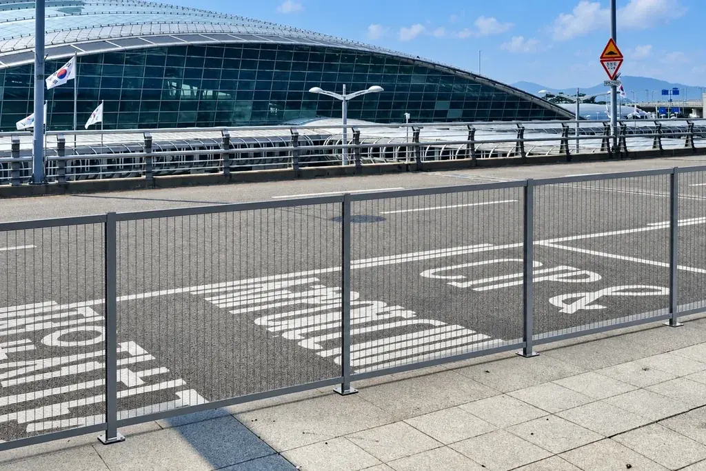
Begin with the mesh, then look beyond it
The term 358 identifies a familiar close-mesh construction rather than a universal security rating. Confirm mesh dimensions and wire diameter on the proposed product drawing, and assess security performance using evidence for the complete system.
On a drawing, distinguish nominal pitch from clear space. For a hypothetical mesh with 12.7 mm centre spacing and 4.0 mm finished wire diameter, the clear distance in that direction is 12.7 − 4.0 = 8.7 mm. This subtraction is valid only if the specified 12.7 mm is a centre spacing. Subtracting wire diameter from a dimension already defined as a clear opening would produce an incorrect result.
For product comparisons, record the measurement convention once, then compare like with like. Use the 358 construction guide for the underlying terminology.
Measure effective height from the accessible side
The height printed on a panel schedule may not be the height a person encounters. Raised ground outside the fence, a retaining wall or stacked materials can reduce the vertical distance to the top.
Suppose a panel top is 2,400 mm above the original ground datum. A permanent raised surface on the approach side finishes 350 mm above that datum. The exposed height above that surface is:
2,400 − 350 = 2,050 mm.
That is a geometry example, not a recommended anti-climb height. It shows why the survey needs actual accessible levels along both sides, particularly near ramps, retaining structures and gate thresholds.
Use a common survey datum and mark the height at every level change. A single photograph from the lower side can conceal the problem.
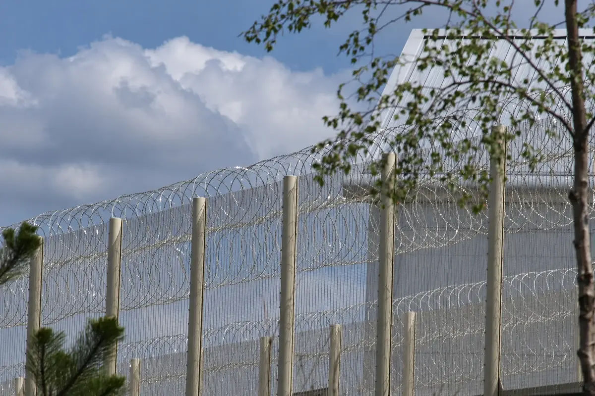
Walk six parts of the approach
- Approach area: record containers, bins, stored materials, trees and equipment near the boundary. Note whether these are permanent or can move during normal operations.
- Mesh face: inspect openings, damaged wires and any added items that create footholds.
- Supports and rails: check the accessible face for brackets, horizontal members and service conduits that change the climbing route.
- Gate zone: review hinges, locking boxes, centre joints and gate-to-fence transitions.
- Top line: identify changes in height and the ends of any topping. Check that topping supports match the specified assembly.
- Adjacent structures: follow the connection to walls, roofs, drainage structures and neighbouring fences.
Record each observation by location and photograph direction. “Vegetation along fence” is too broad to assign work. “Shrub touching panel A17 and obscuring the gate-side joint” allows a maintenance team to act and a supervisor to verify completion.
Turn observations into a useful action register
| Example observation | Measurement or evidence | Practical response |
|---|---|---|
| Raised paving beside a panel | Relative ground level and top elevation | Review the local height and transition detail |
| Stored goods against the fence | Location, footprint and access route | Relocate storage and mark a controlled storage limit |
| Exposed gate cross-member | Drawing plus accessible-side photograph | Review leaf construction and local guarding |
| Added sign on the mesh | Size, fixing method and position | Check climbing access and structural effect |
| Damaged upper joint | Missing parts and joint movement | Restrict access and restore the approved connection |
Do not assign every item the same urgency. A loose panel that opens the boundary needs immediate control. A future landscaping change needs a documented design decision before work starts. A changed storage practice needs an operating rule as well as a one-off clearance.
Review modifications before they become permanent
Privacy strips, banners and equipment can change the fence after installation. Besides providing purchase points, they can change wind loading and visibility. A maintenance work order should therefore identify attachments that were not on the original drawings.
For an illustrative sign measuring 1.2 × 0.8 m, the gross face area is 0.96 m². That number can be added to the modification record. It is not enough to calculate the resulting load without pressure, exposure, support and connection information.
Photograph approved attachments and label their fixing locations. This gives future inspectors a practical reference rather than relying on memory of how the fence looked at handover.
Keep deterrence, delay and detection distinct
A fence can discourage casual climbing without carrying a tested delay rating. Detection devices and cameras perform another job: they indicate or help assess an event. A higher fence cannot compensate for an unattended alarm, and a camera does not repair an open joint.
Finish the review with three separate outputs: a marked-up physical boundary drawing, an action register with responsible owners, and a list of any required performance evidence. Where a tested rating is specified, match the complete installed configuration to the relevant evidence. Use the connection inspection guide to examine the joints that hold that configuration together.