
By FencingWise Editorial Team · Updated 17 September 2026.
Start with the connection drawing
Identify the approved detail for each location. Line posts, ends, corners and gate interfaces may use different parts. An inspector needs the part reference and assembly order, not merely a photograph of a similar completed fence.
A connection drawing should show which component bears against the mesh, the location of any spacer or insert, the bolt route and the retention method. If a security fixing has a sacrificial head, record when its final installation is permitted. Breaking it off before alignment checks can make correction unnecessarily destructive.
Use the clamp-bar versus clip comparison to understand the different contact arrangements. Neither arrangement can be judged solely by counting visible fixings.
Follow the force through five interfaces
Trace the connection in this order: mesh edge, clamp or clip, bolt assembly, post wall or bracket, and post support. At each interface ask whether the specified parts are present and actually engaged.
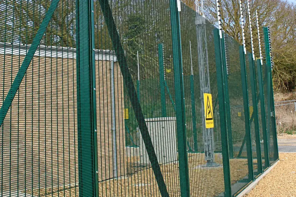
For example, a clamp can be tight against a spacer while leaving the mesh loose. A bolt can be long enough overall but have the wrong unthreaded shank length for the assembly. A corner bracket can hold one panel correctly while the returning panel sits outside its intended contact area.
Observe without applying an improvised proof load. Where testing is required, use the specified method and equipment. A person pulling on a panel does not reproduce a controlled connection test.
Count connection positions without doubling shared parts
Assume an illustrative straight fence has 24 bays and 25 posts. Its approved detail calls for 7 fixing positions per post, with one assembly at each position securing the relevant panel edges at that post.
The expected total is:
25 × 7 = 175 fixing assemblies.
Counting seven assemblies on each side of every panel would instead give 24 × 2 × 7 = 336. That would be incorrect for this shared-post detail. It could be appropriate for a different detail with independent edge fixings, which is why the assembly drawing controls the count.
If inspection records 3 missing assemblies and 2 incomplete assemblies, there are 170 complete positions out of 175, or approximately 97.1%. The five defects still require action. A high completion percentage does not make a local opening acceptable.
Use a defect description that leads to a repair
| Observation | Evidence to record | Required follow-up |
|---|---|---|
| Missing assembly | Post, height position and part reference | Fit the specified complete assembly |
| Mesh outside clamp contact | Front and rear photographs | Re-seat using an approved method |
| Loose connection | Location and verified test method | Establish cause before tightening |
| Wrong fixing length | Measured assembly and component identification | Replace against the drawing |
| Cracked post or damaged hole | Extent and surrounding distortion | Obtain a structural disposition |
| Coating damaged at the joint | Area, depth and exposed layer | Apply the appropriate repair system |
“Loose bolt” and “missing torque mark” are not interchangeable. A witness mark can help reveal later relative movement, but it does not prove that the correct installation torque was applied. Conversely, the absence of a mark is only a defect if the project requires marking.
Do not use a generic torque figure taken from a bolt diameter chart. The selected fastener, material, coating, locking arrangement and component strength can affect the correct installation method.
Give corners and gates their own inspection positions
At a direction change, look for unused holes, improvised packing and poor panel overlap. An installer may have aligned the straight runs successfully while leaving the corner connection unresolved.
At a gate post, check how the fixed fence terminates independently of the moving leaf. The leaf should not have to close to hold the neighbouring panel in place. Where a transition uses a separate bracket, record it as a separate component rather than assuming it is part of the gate frame.
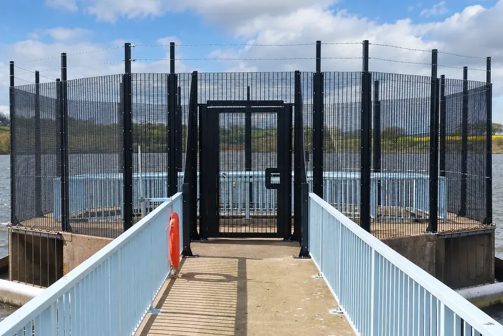
Low connections deserve particular attention after landscaping. Soil, vegetation and paving can conceal missing parts and make future tool access difficult. Photograph these interfaces before they become obscured.
Close defects against the same register
Assign one record to each defective location. Include the proposed action, the person responsible, the correction date and the verification result. Several similar defects can share one cause investigation, but each location still needs a closure status.
For a lot with repeated missing washers, inspect the affected packing and installation sequence. Replacing only the first visible washer leaves the process problem unresolved. For a damaged hole, adding a larger washer without approval may conceal the defect rather than restore the design.
Keep the final connection map with the handover documents. It becomes a baseline for maintenance teams and helps them distinguish original details from later field modifications.