
By FencingWise Editorial Team · Updated 17 September 2026.
The choice should begin with the specified joint and its evidence. A bar is not automatically a stronger substitute, and adding more clips does not automatically reproduce a bar connection.
Compare the contact with the actual wire arrangement
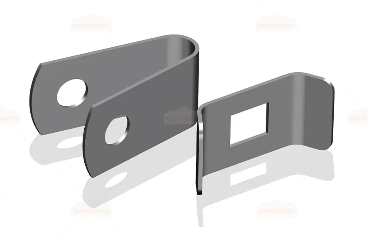
A bar extends along a defined length of panel edge and is secured at specified fixing positions. Separate clips contact the mesh at individual locations. The bar can cover part of the edge between fasteners, whereas a clip arrangement leaves the intervening detail exposed.
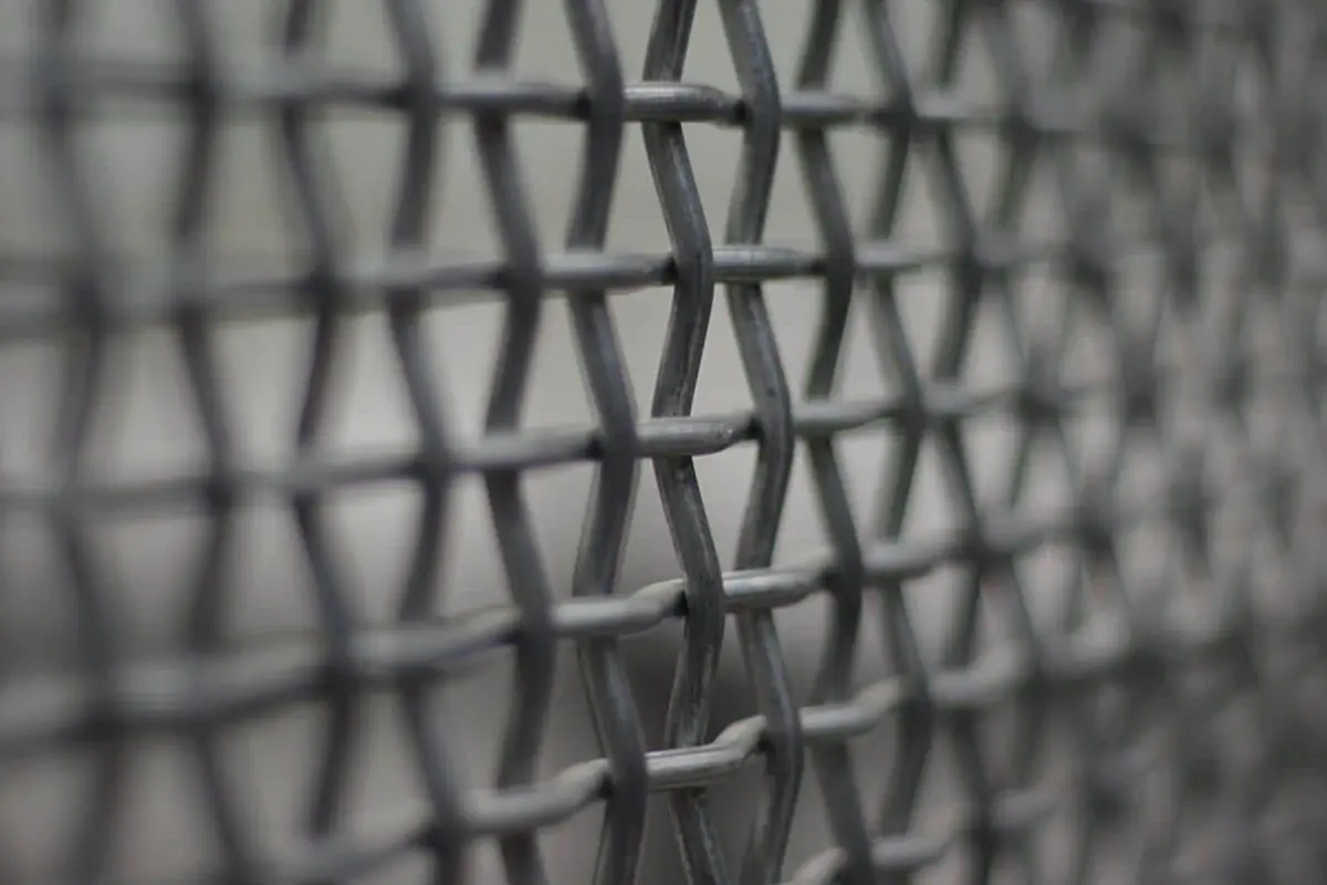
That description still leaves several variables: bar width and thickness, post face, overlap, spacers, bolt arrangement and wire dimensions. A nominally full-height bar may be interrupted at a step or gate connection. A clip may capture one panel edge or a shared pair.
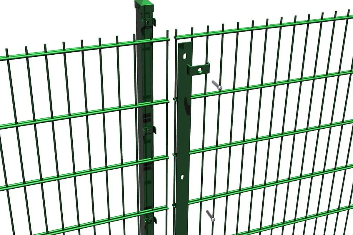
A close-mesh panel can use a bar to capture its overlapping edge, while a twin-wire design can use individual clips. These are examples of specific joint arrangements. Identify the mating panel and post before treating a similar-looking fixing as a replacement.
Draw the joint through its thickness
A section through the connection should identify, in order, the fastener head, washer where specified, fitting, captured panel, spacer if present, post or support, and the receiving thread or nut.
A simple example demonstrates why substitutions need review. Suppose a hypothetical joint contains a 3 mm clip, a 2 mm washer, an 8 mm captured assembly depth and a 3 mm support wall. The stated stack before the receiving thread or nut is 16 mm.
Replacing the clip with a 6 mm bar makes that stack 19 mm, an increase of 3 mm. This does not determine the required bolt length: thread engagement, nut dimensions, washers on the other side and the actual geometry still need to be included. It identifies why an existing fastener cannot be assumed suitable.
The same logic applies to coatings and inserts. Check the finished assembly rather than approving parts solely from their bare dimensions.
A 20-panel counting example
Assume an illustrative straight fence of 20 panels, with separate connections for each of their two vertical edges. There are:
20 × 2 = 40 independently connected panel edges.
For the clip option, assume four complete clips per edge. For the bar option, assume one bar per edge and four fastener positions per bar.
| Item | Hypothetical clip arrangement | Hypothetical bar arrangement |
|---|---|---|
| Panel edges | 40 | 40 |
| Clips | 40 × 4 = 160 | 0 |
| Bars | 0 | 40 |
| Fastener positions | 160 | 40 × 4 = 160 |
Both examples have 160 fastener positions, but their fittings are different. This is a counting exercise only; four positions are not an installation recommendation or a claim of equivalent performance.
If the actual system uses a shared fitting for neighbouring edges, this calculation must change. Identify that joint before multiplying quantities.
Access can decide whether a proposed connection is practical
A long bar may require access along much of the post face for positioning and alignment. A clip allows local placement, but each fastener still needs the specified tool and room to operate it.
At a corner, lay out the fittings on both post faces. A bolt from one direction may obstruct the fitting from the other. At a wall return, the receiving nut may be inaccessible. At a stepped bay, a bar intended for a level joint may cover the wrong parts of the two panel edges.
These are geometric questions that a trial joint can answer before a full order is produced. Record the actual tool clearance and removal path, rather than describing a fixing as “easy to install” without examining the site position.
Run a structured trial assembly
- Select the approved panel, post, fittings and fasteners by part code and revision.
- Place the panel in the intended orientation and support it appropriately.
- Check that the contact surfaces seat as shown before tightening.
- Assemble to the component instructions, including the specified tightening procedure.
- Examine both adjoining edges and any spacers, overlaps or exposed projections.
- Record whether replacement requires removal of one panel, two panels or a longer bar.
The trial confirms fit and assembly access. It does not replace structural, security or other performance evidence required for the fence.
Photograph the joint from the face and side. A completed front view alone can hide an incorrectly seated spacer or insufficient receiving-thread engagement.
Include replacement work in the comparison
With independent clips, a local fitting can sometimes be replaced without removing a full-height component, subject to the system's support and safety procedure. A shared bar may hold two adjoining panels, so releasing it can affect both. The work method must account for that dependency.
Anti-tamper hardware also changes future access. A permanent fastener may require replacement during authorised maintenance, while another arrangement is designed for removal with controlled tooling. The fastener selection article explains that distinction.
Carry those consequences into the spare-parts schedule. Stocking the correct panel but the wrong bar length or clip depth can leave a repair incomplete.
Make a like-for-like buying decision
For each option, retain the joint drawing, component quantities, installation access and applicable evidence. Compare complete connection packages rather than the price of a bar against the price of one clip.
If a tested fence configuration specifies a particular fixing arrangement, a proposed alternative needs the relevant approval. For an untested general boundary, the connection still needs to meet its design requirements. In both cases, a trial fit and a counted BOM turn a visual preference into a practical purchasing decision.