
By FencingWise Editorial Team · Updated 17 September 2026.
Begin with the approved bolt or nut specification, then decide how authorised removal should work.
Separate three different requirements
| Requirement | Question to answer | Evidence or detail needed |
|---|---|---|
| Mechanical connection | Does the fastener secure this particular assembly? | Thread, material, dimensions, engagement and connection design |
| Resistance to unauthorised removal | What makes ordinary removal more difficult? | Head or nut design and tooling arrangement |
| Maintenance access | How will an authorised team replace the part? | Removal procedure, tools and replacement components |
A fastener can satisfy one requirement while failing another. A difficult-to-remove nut is unsuitable if it does not seat correctly or leaves insufficient thread engagement. A mechanically suitable ordinary bolt may not meet the site's tamper-resistance brief.
Anti-tamper and anti-loosening are also different functions. Do not assume a special drive pattern replaces a specified locking feature, or add a locking product without checking compatibility with the connection instructions.
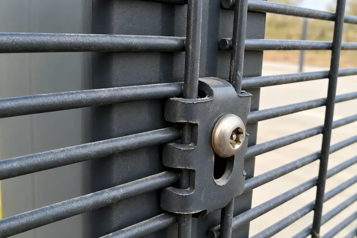
Decide between permanent and serviceable arrangements
Some security fasteners are intended to remain permanently installed; others can be removed using the appropriate controlled tool. That difference should appear in the maintenance plan before an order is placed.
A shear nut can use a driving portion that breaks away at its specified installation torque, leaving a conical nut. Use the selected fastener's installation instructions; there is no universal installation torque for all shear nuts.
A serviceable security fastener can be appropriate where panels need planned access or periodic replacement. A permanent arrangement may fit another security brief, provided the owner accepts the authorised removal and replacement procedure. Avoid describing either choice as impossible to defeat.
Specify the thread as well as the visible head
A description such as “M8 security bolt” identifies only part of the item. The purchase line should also state thread pitch where relevant, length and its measuring reference, material or grade, finish, head form, matching nut or receiving thread, and any washer or spacer.
Two bolts can pass through the same clearance hole yet have different thread pitches. They are not interchangeable with one receiving nut. Likewise, a matching nominal diameter does not prove sufficient engagement once a thicker clip or coating is introduced.
Trial the complete finished joint. Do not use the exposed bolt length in a photograph as a substitute for an engagement measurement. The acceptable engagement and tightening procedure belong to the specified connection or component instructions.
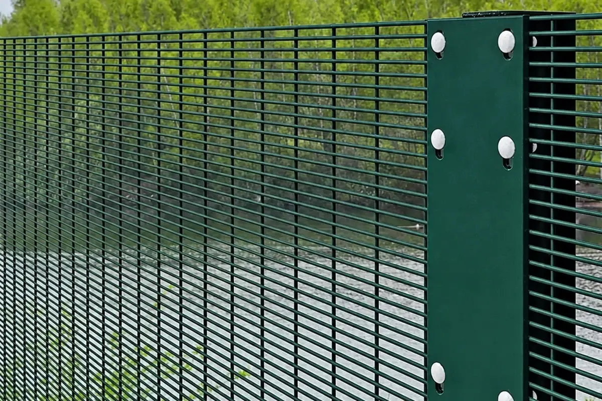
Calculate the assembly stack before choosing length
Use a section drawing to list the clamped parts. For illustration, assume a through-bolted connection with:
- 4 mm fitting.
- 2 mm front washer.
- 6 mm combined captured-component thickness.
- 3 mm support plate.
- 2 mm rear washer.
The thickness before adding the nut and required thread projection is:
4 + 2 + 6 + 3 + 2 = 17 mm.
If a revised fitting is 7 mm thick, the stack becomes 20 mm. That three-millimetre increase must be considered when selecting the bolt.
The example does not prescribe a bolt length, engagement or torque. Those depend on the actual hardware and design. Its purpose is to stop a common error: retaining a fastener because its diameter still fits after the surrounding parts have changed.
Count service parts explicitly
Assume a fictional fence contains 12 panels, with four independent fastener positions on each vertical panel edge. The installation quantity is:
12 × 2 × 4 = 96 complete fastener assemblies.
If the purchaser deliberately adds four spare assemblies, the order quantity becomes 100. Record “96 installation + 4 spare”, not simply “100 required”.
For each assembly, define the bolt, nut, washers and any dedicated tool. Tools are separate order lines; a pack of security fasteners does not necessarily include a driver. Where permanent nuts are used, replacement stock should contain the parts required after authorised removal, not only spare bolts.
Do not generalise four fixing positions to other systems. Count from the approved joint and panel layout.
Check installation without inventing a torque
Before installation, verify part codes, finish, correct tooling and the procedure supplied for the connection. Assemble a trial joint to reveal access or seating problems before repeating it along the boundary.
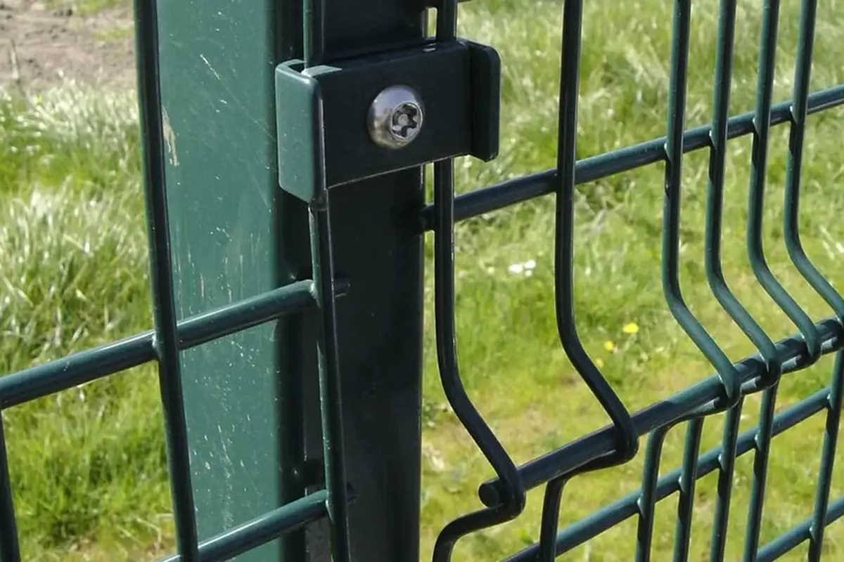
After installation, record the specified completion evidence. For a breakaway design, confirm the expected final condition in accordance with its instructions. For a removable design, record the required tightening verification. A special head does not prove correct preload merely because the tool fits it.
If a fastener behaves unexpectedly, stop and investigate the affected components and procedure. Do not increase torque simply to force a poor-fitting clip onto the mesh or to make the visible result resemble another installation.
Keep future access controlled and documented
The handover record should identify fastener codes, where they are used, the authorised removal method and who holds the tools. Avoid leaving an unlabelled special driver in a mixed bag of site consumables.
A replacement request then becomes specific: which joint, which fastener and which revision, rather than “the unusual bolt on the fence”. The clamp and bracket guide helps identify the surrounding assembly, while handover documentation shows how to preserve the information for maintenance.
That combination provides useful tamper resistance without making routine authorised repair depend on guesswork.