
Issue a drawing that defines the pattern
Record the clear internal frame width, bar section, bar count and the way end gaps are treated. A drawing with only overall panel width leaves the fabricator to choose the infill distribution. That can produce a visibly different panel even when the outside dimensions match.
For an illustrative internal width of 1,800 mm containing 17 bars each 20 mm wide, the bars occupy 340 mm. If 18 gaps, including both end gaps, are equal, each gap is (1,800 − 340) ÷ 18 = 81.11 mm.
This is a layout calculation, not a permitted opening for a safety barrier or a child-accessible railing. The project requirements determine acceptable openings, height and duty. Once those are defined, the calculation helps translate them into a repeatable fabrication pattern.
Prepare the cutting list with the real section geometry
Distinguish square cuts, mitres, inserted bars and butt joints. State whether a length is an overall finished dimension or the cut length of a component. A frame drawing may show an external width while its horizontal member fits between two vertical members.
An illustrative 6,000 mm stock length can yield eight 700 mm pieces with eight 3 mm saw kerfs if the starting end is already prepared and each piece is separated by one cut. Material used is 8 × 700 + 8 × 3 = 5,624 mm, leaving 376 mm.
That arithmetic does not include additional end trimming, defective material or another cutting sequence. Keep these allowances explicit. It is better to show the real cutting plan than add an unexplained waste percentage to every order.
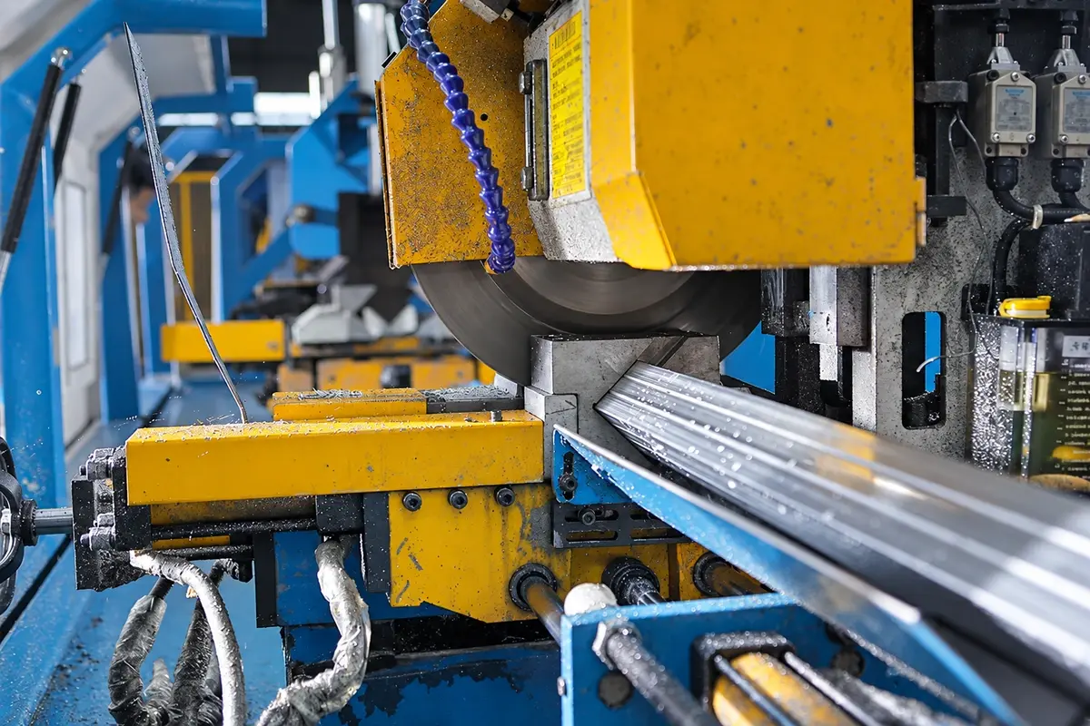
Use the fixture to control geometry, not to hide it
A jig positions components, but worn stops, incorrect inserts or a superseded setup can repeat the same error across a batch. Verify the first assembly against the drawing independently of the jig's labels.
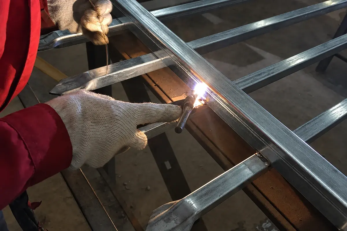
Check frame dimensions, diagonals, bar positions and connection locations before final welding. The production procedure should address welding sequence and distortion control for the actual assembly. Do not prescribe a generic sequence or heat input solely from the panel's appearance.
| Stage | Check | Why it matters later |
|---|---|---|
| Cut components | Identity, length and end condition | Prevents accumulation of fit errors |
| Dry or tack assembly | Pattern, squareness and connection position | Makes correction possible before completion |
| Welded assembly | Weld condition and distortion | Protects final geometry and joint quality |
| Surface preparation | Edges, residues and required treatment | Supports the specified finish |
| Finished panel | Fit, appearance and identification | Connects inspection to the supplied article |
Keep weld acceptance distinct from cosmetic dressing
Grinding a weld smooth does not demonstrate its strength or completeness. Excessive dressing can also change the required joint geometry. Use the specified weld detail, inspection method and acceptance criteria rather than treating a smooth surface as the sole measure of quality.
A visible crack, missing weld or unexplained distortion requires investigation under the inspection process. Where additional testing is required, identify the procedure, sample and result. Do not assign a universal weld-strength figure to all railing products.
For hollow sections destined for hot-dip galvanising, venting and drainage details need coordination with the galvaniser and designer before fabrication. They should not be improvised after the frame is closed. The Galvanizers Association's design-detailing guidance is a starting point for that coordination.
Trial-fit the parts that determine installation
Check the panel-to-post brackets or other connections with the finished dimensions and intended fasteners. Identify left/right orientation and any special corners. A trial fit can reveal clashes, but it does not replace structural verification or the required inspection evidence.
Compare colour and appearance using the agreed sample and conditions. Keep coating thickness or adhesion acceptance separate from a visual colour review. The finish reference explains the different records required.
Preserve the pattern for future replacements
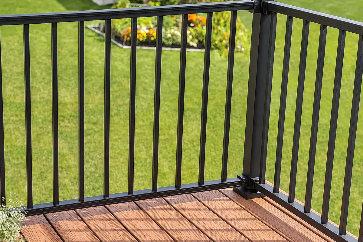
Retain the approved panel drawing, bar count, gap convention, connection detail and finish. A replacement ordered by outside size alone can have a different rhythm of bars or incompatible brackets.
Use the steel railing range to identify the construction family, then keep the actual production and inspection references with the order. That gives both the installer and the maintenance team a reproducible description of the supplied panel.