
Define the supplied panel and the site system separately
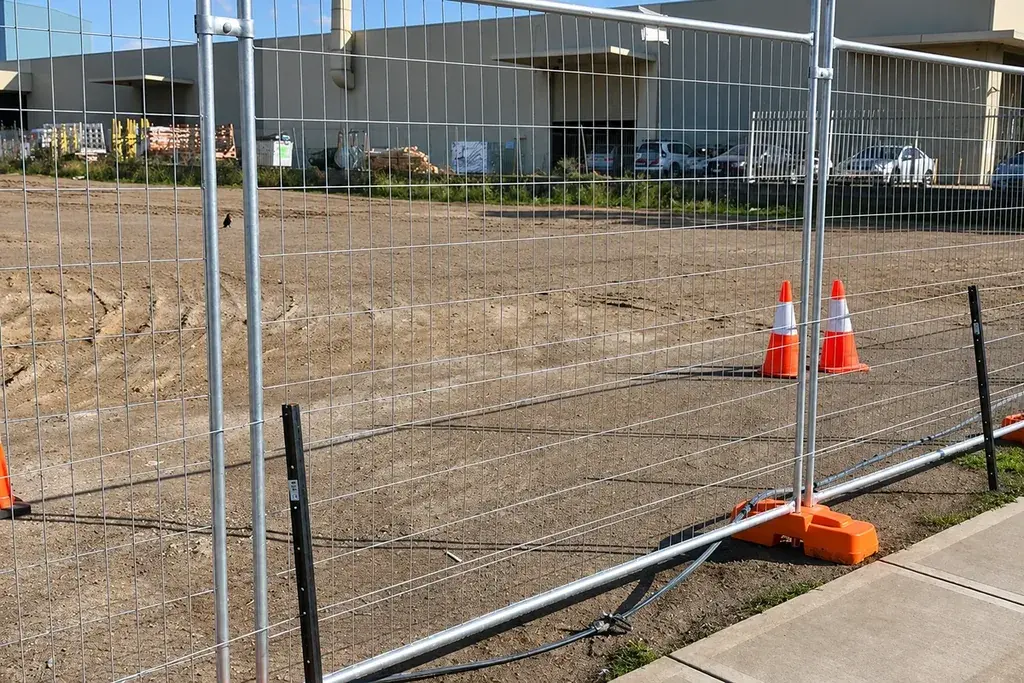
A panel manufacturing drawing should identify frame sections, overall dimensions, mesh construction, attachments and finished surface treatment. The site layout additionally needs feet, clamps, braces, gates and any approved anchorage or ballast arrangement.
A factory inspection of the panel does not establish the wind resistance of every possible installation. Screens, ground conditions, layout and support configuration can change the assembled behaviour. Keep site stability evidence with the actual system rather than assigning it to a generic panel photograph.
The temporary fencing collection distinguishes the principal construction types. This article follows a welded mesh panel through production and inspection without claiming a universal temporary-fence specification.
Verify incoming frame and mesh material
Check the material identity, section dimensions and coating route against the order. For tube, distinguish outside dimensions from wall thickness. For mesh, distinguish wire diameter, pitch and clear opening. Record which values apply before or after any finish.
Do not inherit another manufacturer's material thickness, test frequency or production speed. The accepted drawing and inspection plan define this batch. If a substitute section is proposed, assess its fit and performance implications before it enters the cutting list.
Assign material references that can be carried through to the finished panels where the order requires traceability. A label on an unconnected coil is not enough if it cannot be linked to the production record.
Check the frame before adding the final finish
For a purely geometric example, a rectangular frame measured between defined corners is 2,400 mm wide and 2,100 mm high. Its theoretical diagonal is √(2,400² + 2,100²) = 3,189.04 mm.
Suppose measured diagonals are 3,186 mm and 3,194 mm. Their difference is 8 mm. This observation prompts comparison with the approved squareness requirement; it does not establish acceptance or rejection without that requirement and the measurement method.
Equal diagonals are also insufficient on their own. Check the side dimensions, straightness, joint positions and overall flatness. A frame can be the wrong size while remaining square.
Inspect mesh attachment as its own feature
| Feature | Practical check | Record |
|---|---|---|
| Mesh position | Correct orientation and edge location within the frame | Drawing reference and measured positions |
| Attachment pattern | Required locations present and consistent with the detail | Inspection result and any omissions |
| Weld condition | Visible defects and the specified additional testing | Method, sample and acceptance basis |
| Exposed edges | Cut wires or projections treated as designed | Photographs or recorded observations |
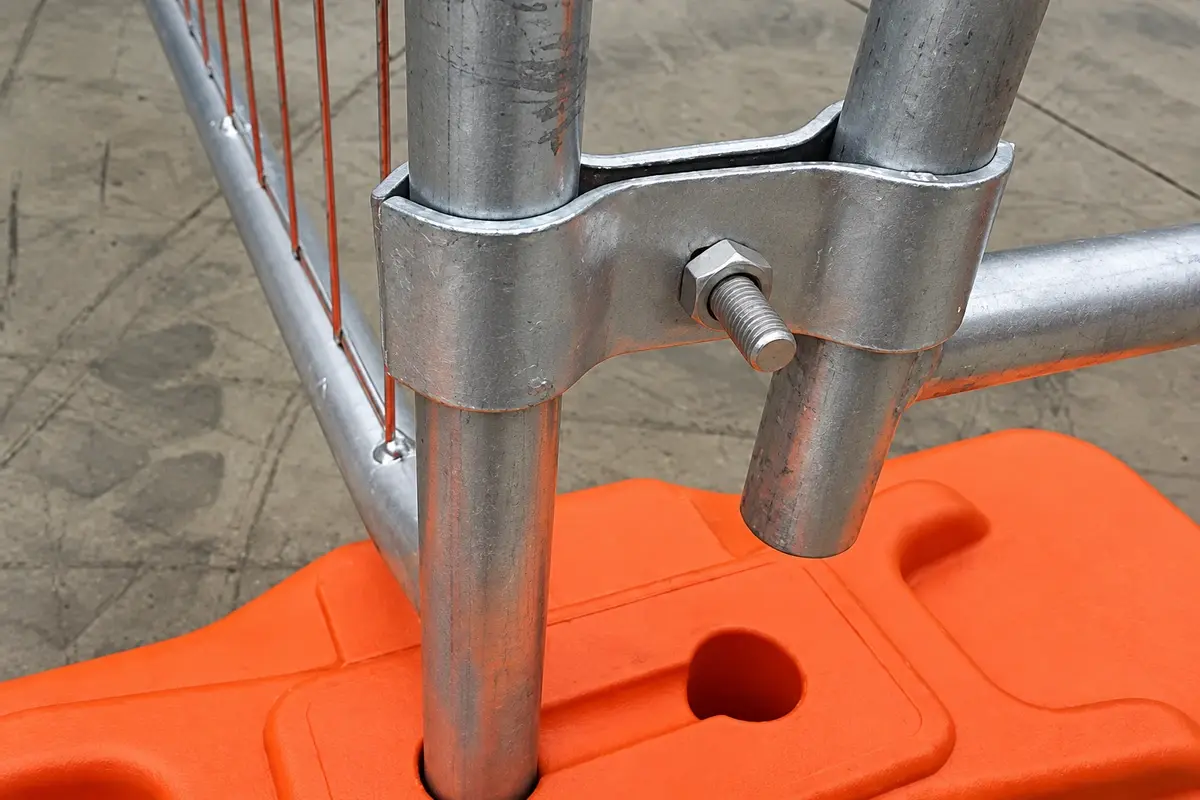
| Frame connections | Clamp and foot interfaces match the intended system | Trial-assembly reference |
A large number of visible welds does not by itself prove attachment performance. Use the specified joint requirements and test evidence. Avoid turning a generic blog's force number into a contractual acceptance criterion.
Trial-assemble representative components
Fit the panel to the intended feet and clamps under an agreed factory trial arrangement. Check dimensional compatibility, access for fastening and any interference between adjacent frames. Include a corner or gate interface where it introduces a different component.
The trial should be controlled and supported safely. It is a compatibility check unless a defined test procedure establishes something more. An unbraced demonstration panel standing briefly indoors is not evidence of outdoor stability.
After finishing, repeat the critical fit checks where coating build-up can affect them. Record the actual fastener and clamp references, not only a note that the panel fits.
Inspect and pack for repeated handling
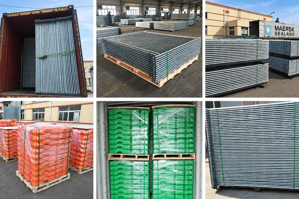
Protect contact points that can rub through coatings during transport. Keep projections from damaging adjacent panels, and group small components so quantities remain checkable. Packing instructions should identify the intended handling method and the pack information needed by the receiver.
For an illustrative delivery of 240 panels in packs of 20, the order has 12 packs. If one pack is split into two groups of 10 for handling, the panel total remains 240 but the package count becomes 13. Update the packing list instead of leaving receiving staff to reconcile an unexplained extra package.
Release with the correct evidence boundary
The production record should link material identity, dimensions, weld inspection, finishing and packing to the batch. Any site-specific support or wind documentation should identify the complete installation configuration separately.
Use the pre-shipment inspection guide to organise the final review. The result should demonstrate what was actually inspected and supplied, without converting factory workmanship checks into an unsupported promise about every future site arrangement.