
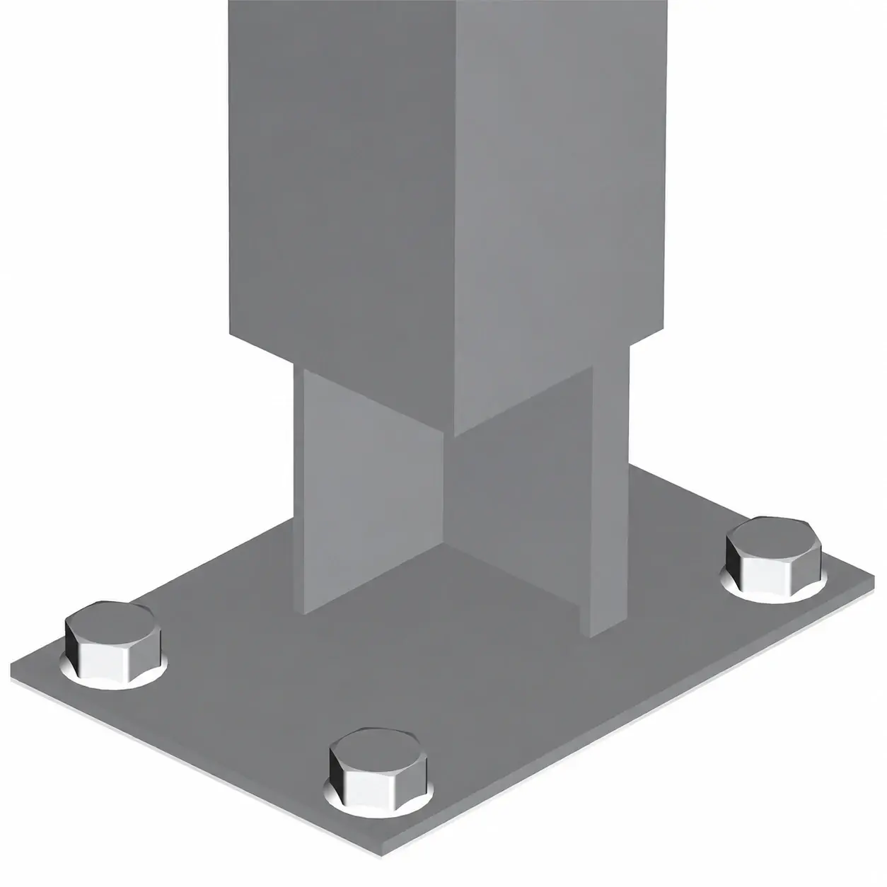
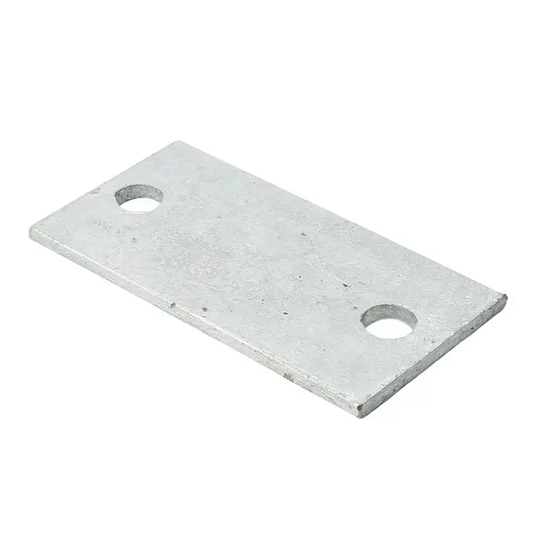
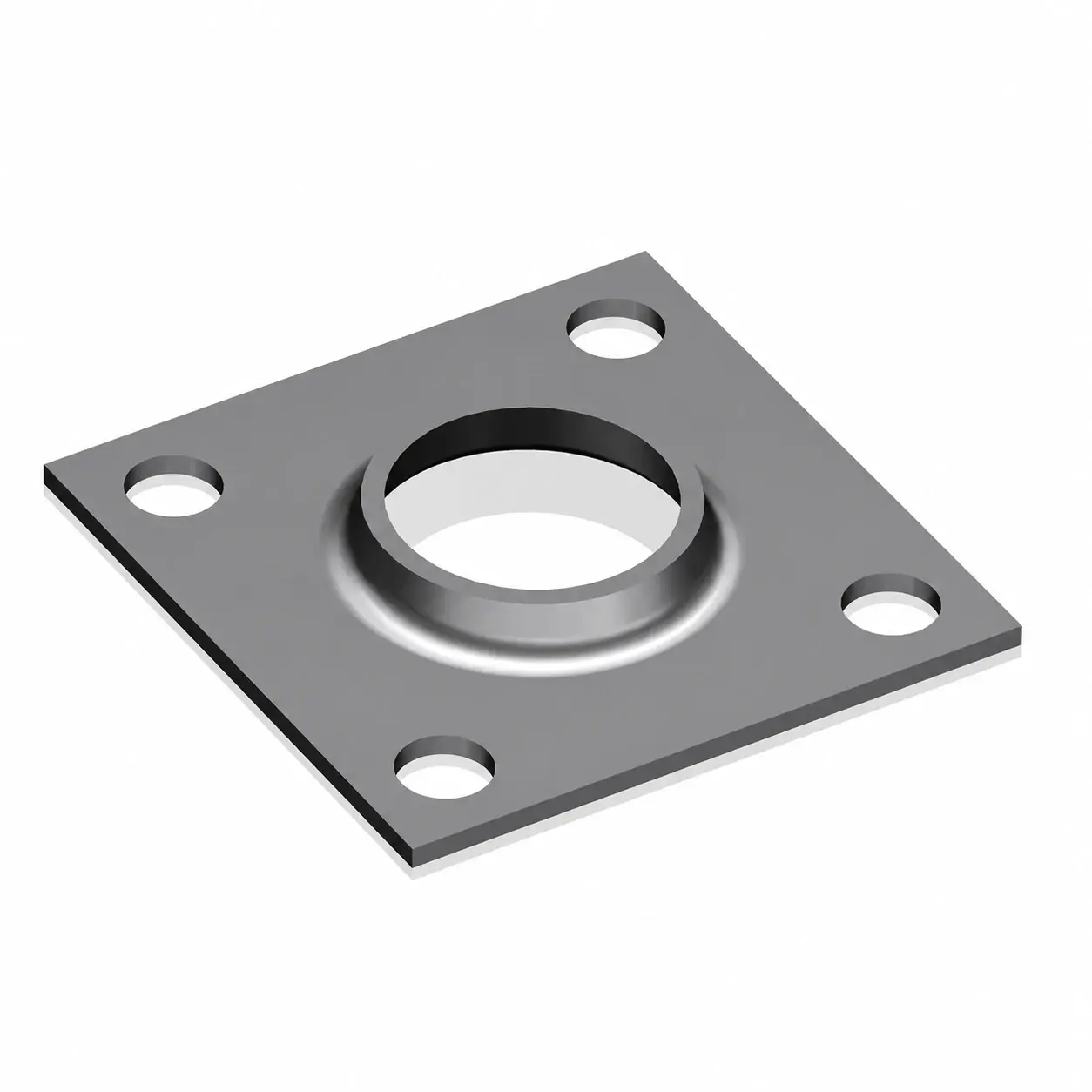
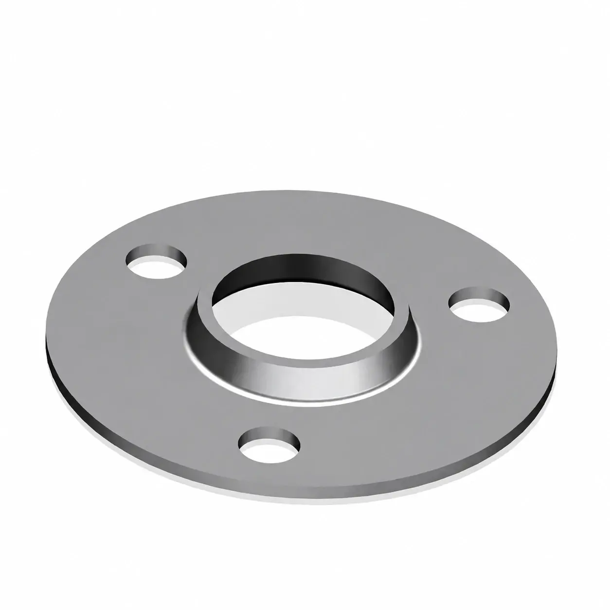
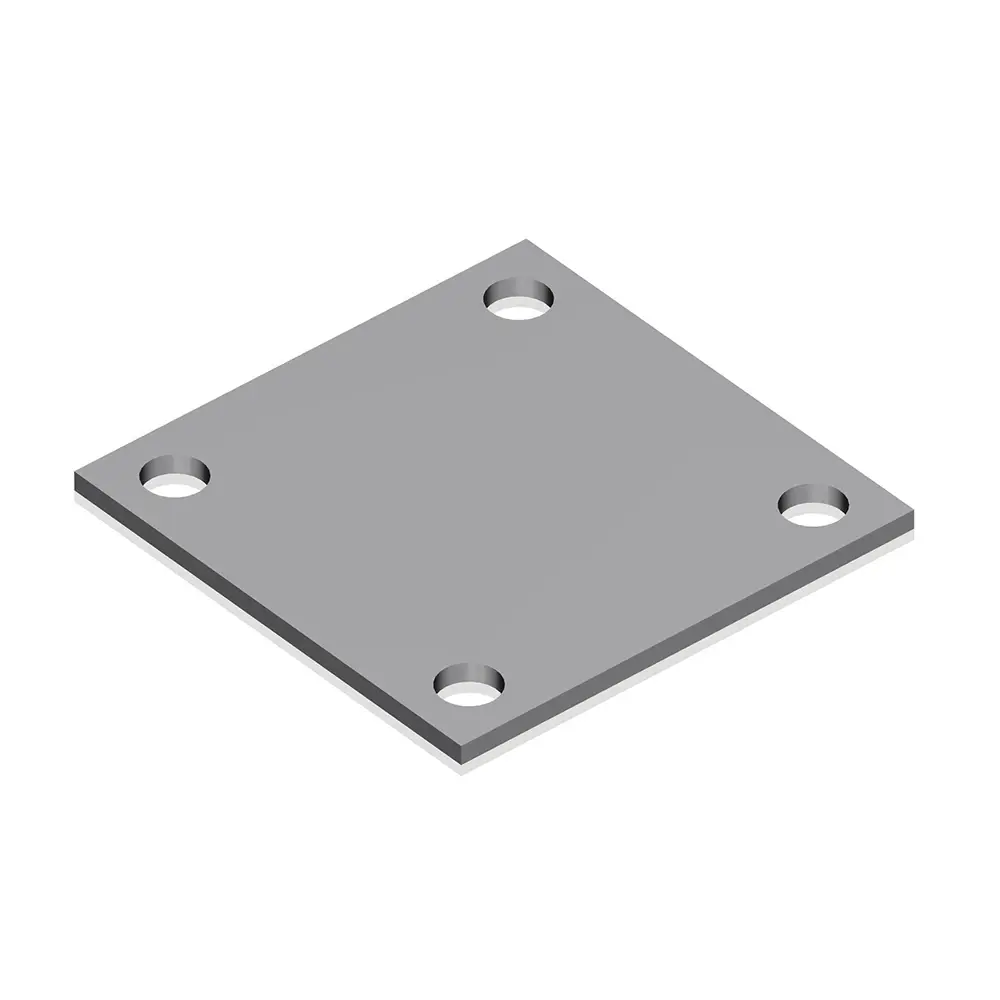
Read the plate in plan and section
The plan view should locate the post and every fixing hole from consistent datums. The section should identify plate thickness and the post attachment. For slotted holes, include both dimensions and the slot direction.
Mark the fence-line direction on the drawing. This avoids rotating a rectangular post or asymmetric hole pattern into the wrong position during manufacture or installation.
| Drawing item | Purpose |
|---|---|
| Plate outline and thickness | Identifies the fabricated part |
| Hole centres and sizes | Coordinates the fixing layout |
| Post location | Shows offsets and orientation |
| Attachment detail | Defines how the post and plate are joined |
| Finish requirement | Covers the completed component and exposed edges |
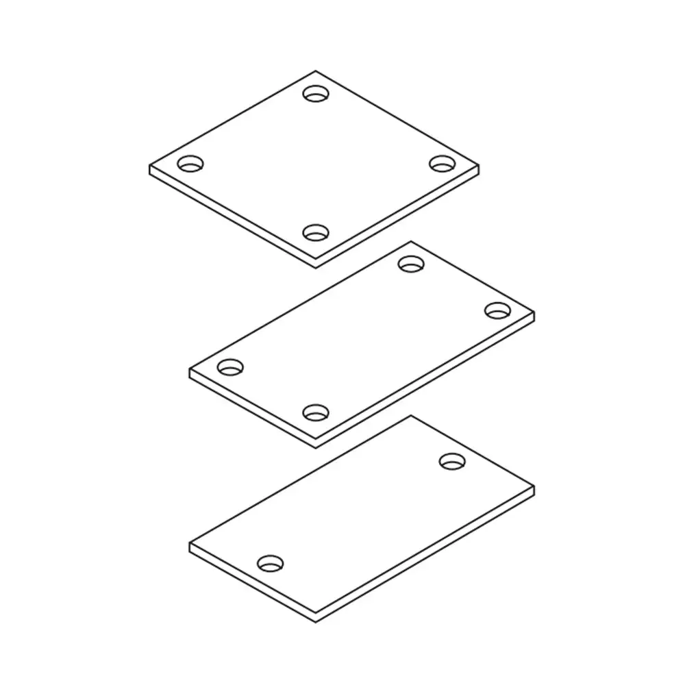
The supporting structure is part of the decision
The project design must account for the supporting material, edge distances, anchor arrangement and loads. An existing slab or wall cannot be assumed suitable merely because the plate can be placed on it.
For that reason, an anchor diameter is not selected from the hole diameter alone. Use the anchor and foundation details established for the project. FencingWise supplies against the agreed component specification; the structural design remains a separate project responsibility.
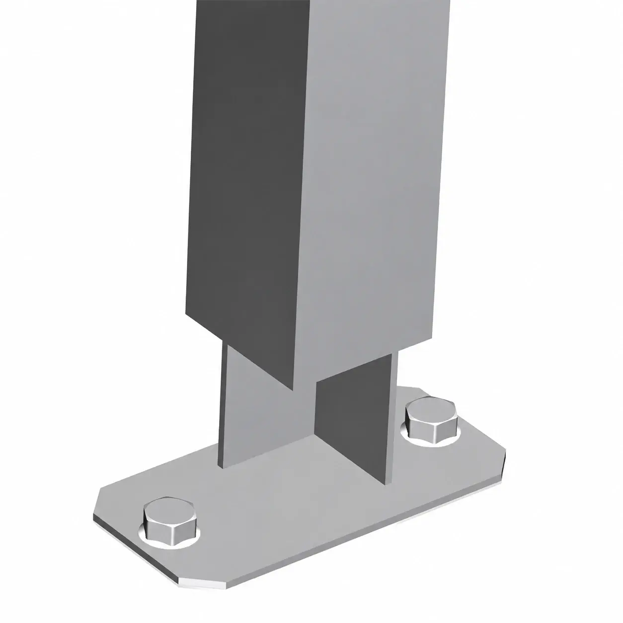
Loose plates or completed posts?
Distinguish loose fabrication parts from finished base-plated posts. A completed post order needs the overall height and post orientation as well as the plate dimensions. If fabrication or coating occurs after supply, identify that work in the purchasing scope.
List anchors, washers, covers and other accessories separately. For replacement work, measure the existing pattern and provide the post reference; drilling additional holes can change the designed connection and should not be treated as an automatic adjustment.