
Draw the whole path of travel
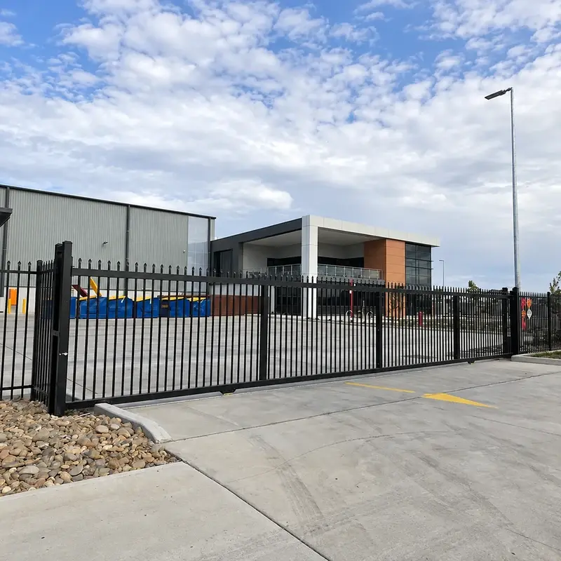
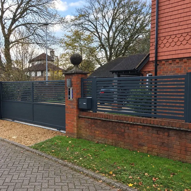
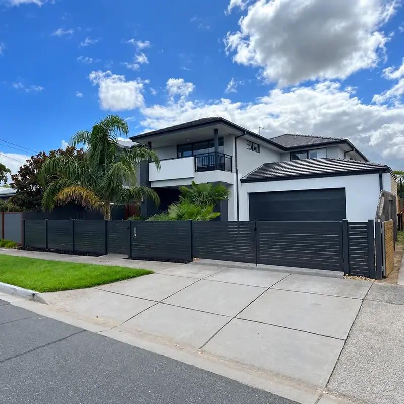
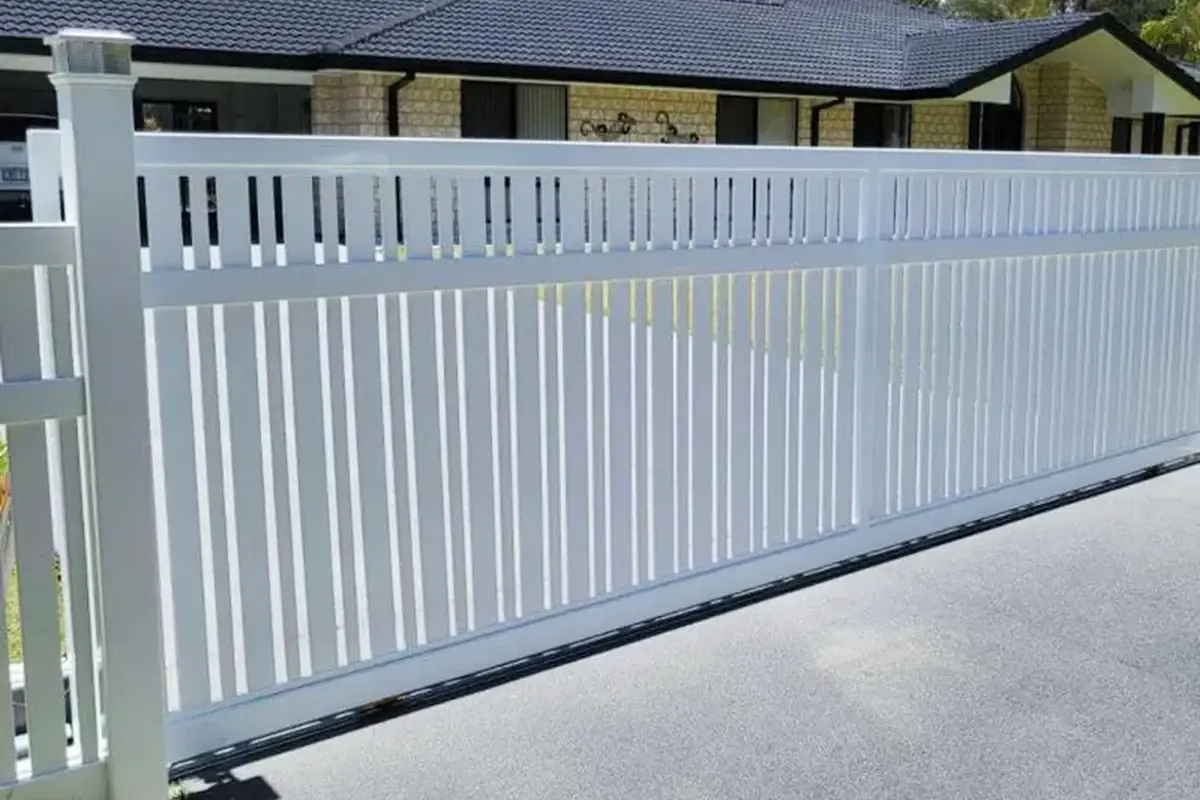
Mark the gate in its open and closed positions. Include fence returns, walls, equipment and parked vehicles near the travel area. The clear opening alone does not establish the length of the moving leaf or the space it needs beside the entrance.
Show ground levels and drainage along the track route. The supporting surface and running system must suit the gate and the site's vehicle movements.
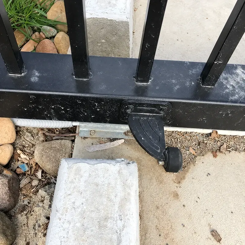
Match wheels, track and guides
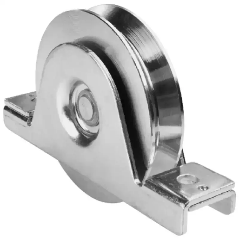
A wheel profile must match the track it runs on. Guides and stops have separate roles in controlling and retaining the leaf. List those components by reference instead of describing them as an unspecified “sliding kit”.
| Interface | Detail for the drawing |
|---|---|
| Ground | Track profile, supporting surface and levels |
| Leaf | Frame, infill and wheel attachment |
| Upper guidance | Guide position and clearance |
| End positions | Stops, receivers and retention arrangement |
| Fence | Separation from moving parts and access for maintenance |
Define manual and powered operation separately
If automation is intended, coordinate the operator, controls and protective measures with a competent specialist. The complete installation needs assessment for its particular location; buying a gate leaf and motor separately does not establish the safety of the finished system. See the HSE guidance on powered gate safety.
FencingWise's quotation should distinguish the gate material package from civil works, electrical installation and powered-system commissioning.
Keep the running route maintainable
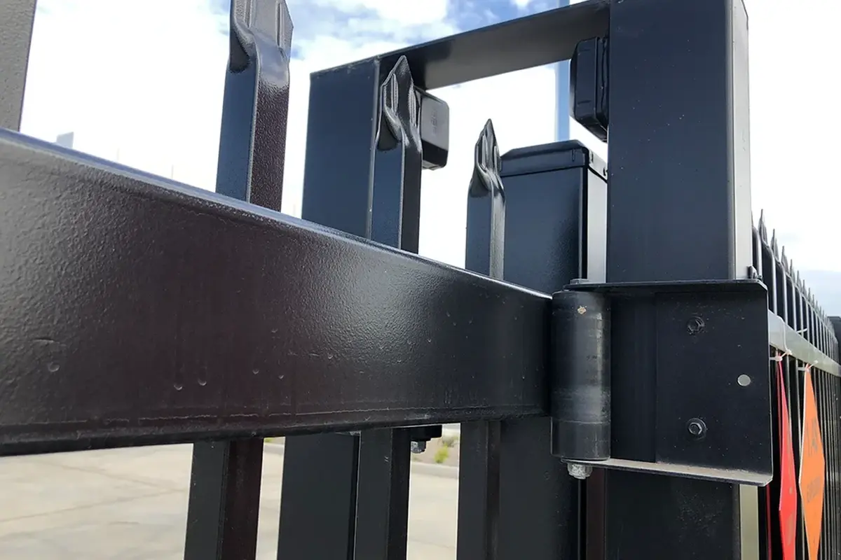
Provide access to inspect and clean the track and inspect the specified running components. Record wheel, guide and lock references for spare parts. Any changes to the infill or operating equipment should be reviewed against the gate design before modification.
For an entrance with suitable swing space, compare 358 vehicle gates when setting the project brief.