
By FencingWise Editorial Team · Updated 17 September 2026.
Identify the actual structural support
Establish whether the visible surface is structural concrete, a topping, paving, masonry or another material. Record the supporting element's thickness, condition and relevant design information.
A thin paving slab over bedding is not equivalent to a designed concrete foundation. A screed or coating also changes the relationship between the top surface and the structural material below.
Locate services and reinforcement using the appropriate site procedure before drilling. Mark no-drill areas and resolve conflicts through the design rather than moving holes ad hoc.
Compare the base plate with the anchor layout
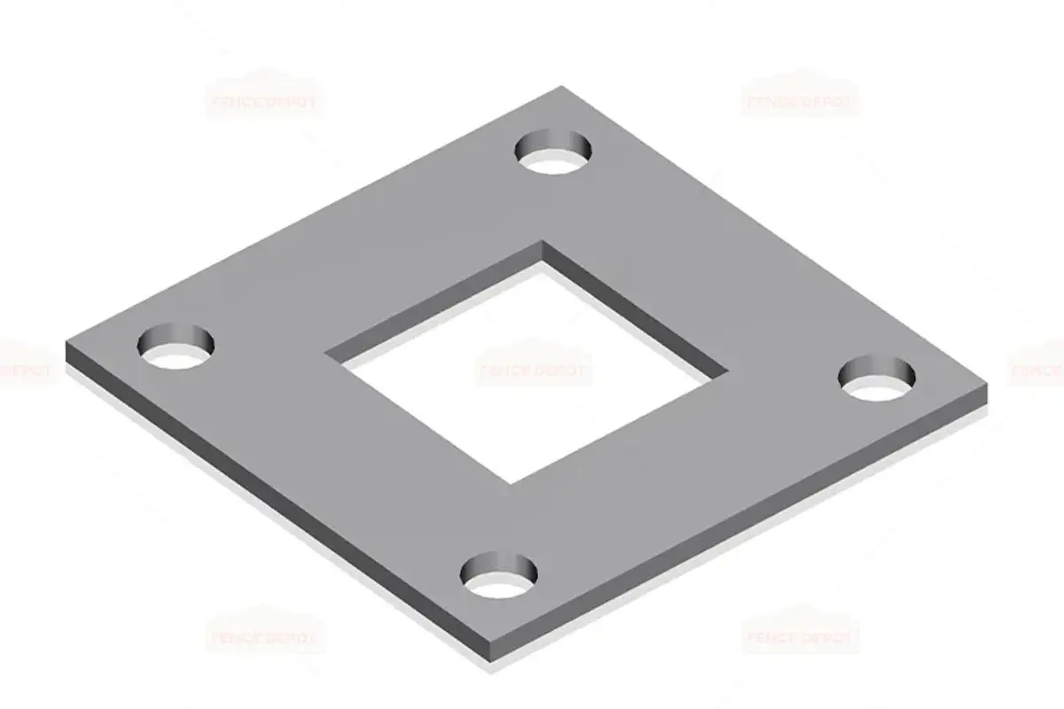
Record plate length and width, thickness, hole diameter or slot dimensions, hole-centre spacing, post position and orientation. Compare those dimensions with the selected anchor design and installation instructions.
Use a template or measured drawing to check the full pattern. A single matching hole does not establish that all anchors can be installed correctly.
For an illustrative 200 × 200 mm plate with a centred square hole pattern of 140 × 140 mm, each hole centre sits 30 mm from the plate edge:
(200 − 140) ÷ 2 = 30 mm.
That is a plate dimension, not the anchor's distance from the edge of the concrete.
Calculate concrete edge distance separately
Suppose that plate is positioned with its nearest edge 40 mm from a concrete edge, and the nearest hole centre is 30 mm inside the plate. The anchor-centre distance to the concrete edge is:
40 + 30 = 70 mm.
Whether 70 mm is acceptable depends on the anchor, loads, concrete and design. It is not a generic minimum.
If the post is shifted 20 mm toward the edge to improve the fence alignment, the distance falls to 50 mm. A small layout adjustment can therefore change the anchorage condition materially.
Check all relevant edges, including corners and openings. The nearest visible outside edge is not always the controlling one.
Use the exact anchor's installation information
The selected anchor system's instructions should identify drilling, embedment, cleaning, setting and any curing conditions. Check these requirements before installation.
Hole-cleaning methods depend on the anchor system. A procedure used successfully for one anchor should not be assumed valid for another.
Do not borrow a torque value from a similarly sized fastener. The required installation torque, where applicable, belongs to the actual anchoring system and assembly.
Hold installation at the points that cannot be checked later
| Hold point | Evidence before proceeding |
|---|---|
| Support released | Material, condition and design requirements resolved |
| Layout accepted | Post line, orientation, hole pattern and edge distances checked |
| Hole completed | Diameter, depth and drilling method recorded |
| Hole prepared | Specified cleaning and condition achieved |
| Anchor installed | Product, batch where required, embedment and setting method |
| Load permitted | Cure or other installation conditions satisfied |
| Plate completed | Bearing, levelling and tightening arrangement accepted |
For bonded anchors, record the relevant material and substrate conditions specified by the instructions. A quoted cure time without its temperature and installation conditions can be misleading.
Where the base plate requires grout, levelling nuts or another bearing detail, follow the designed arrangement. Random washers or packing pieces can change load transfer.
Check the first completed post as a trial

Before repeating the installation, verify post orientation, plumb, elevation and the relationship to a representative panel. Confirm that the base hardware can be accessed and that projecting parts do not create an unintended obstruction.
An example first-post check might find a 10 mm lateral offset while the adjoining panel connection has only 6 mm of available movement in that direction. The remaining 4 mm should be resolved before further holes are drilled.
Do not enlarge a base-plate hole, bend an anchor or cut a reinforcing bar to make the trial fit without an approved disposition. Those actions alter more than appearance.
Release the installation with a traceable record
Record post and anchor identification, support location, as-installed geometry and required inspection results. Keep photographs before grout or covers conceal the work.
If the substrate differs from the design assumption, stop that location and resolve it. The useful outcome of a pre-installation check is a clear decision to proceed, revise the detail or use another support arrangement.
For later alignment issues, use the installation-tolerance guide. It explains how to distinguish a permitted adjustment from a change that needs design review.