
By FencingWise Editorial Team · Updated 17 September 2026.
Separate three different kinds of variation
Manufacturing tolerance describes permitted variation in a component. Set-out tolerance concerns the installed position of supports. Connection adjustment describes the movement available within a particular assembly.
These can interact, but they are not the same allowance. A panel within its manufacturing tolerance can still fail to fit posts installed outside their permitted positions.
Record the governing dimension, datum and acceptance interval for each check. “Within tolerance” is incomplete without identifying which requirement has been assessed.
Use a dimension chain for the actual connection
Consider a simplified panel fitted between two locating faces. Let G be the available distance, P the panel width and a and b the required allowances at the two sides.
The relationship is:
G = P + a + b.
Assume an illustrative design with P = 2,400 mm and a = b = 20 mm. The nominal required distance is 2,440 mm.
If the measured distance is 2,455 mm, the extra 15 mm must be dealt with by permitted connection movement or a revised arrangement. It should not disappear into an unexplained note that the panel is “approximately 2.4 m”.
Check adjustment from the installed position
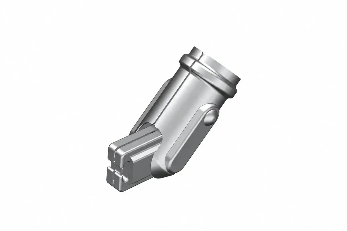
Suppose each side has ±5 mm of available movement from its intended central setting. The two sides together can accommodate up to 10 mm of total increase in this simplified geometry.
The 15 mm discrepancy therefore leaves 5 mm unresolved. Moving both sides to their limits still does not make the arrangement fit as intended.
If one connection was already installed 3 mm away from its central setting, its remaining movement in a particular direction may be smaller. Record actual settings rather than quoting the manufacturer's full theoretical range as if it remains available.
This example does not define a tolerance for any supplied fence. It demonstrates how to evaluate a specific drawing and connection.
Measure from independent survey references
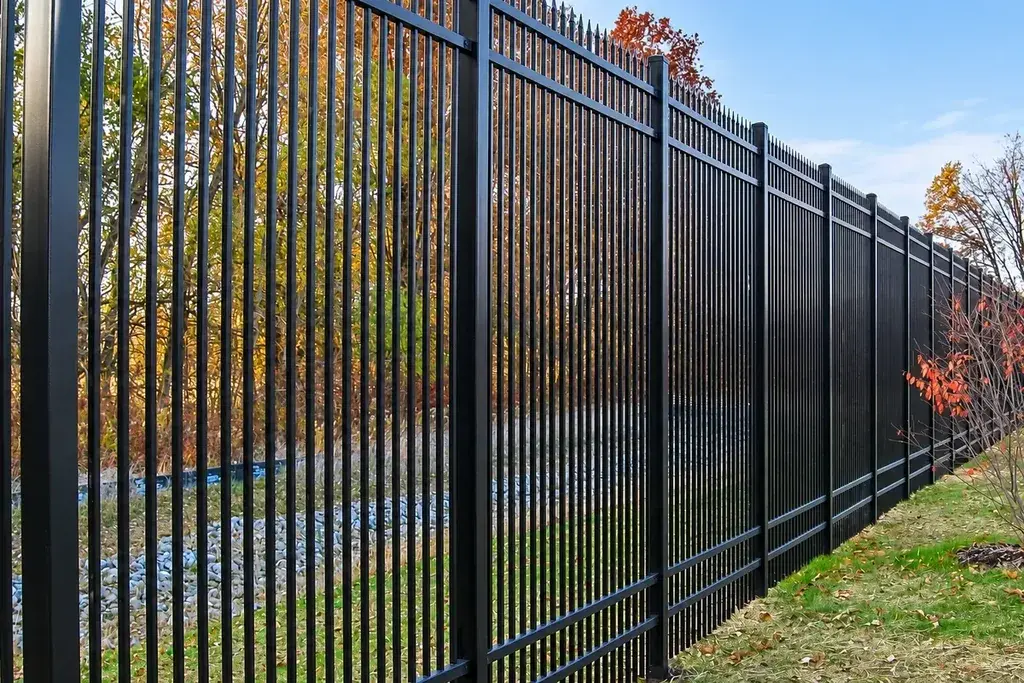
Repeatedly measuring from the previous post can accumulate small errors. Check intermediate stations against the original survey control.
For a hypothetical 16-bay run with a 2,500 mm module, the intended centre-to-centre length is 40,000 mm. An average spacing error of +4 mm per bay adds 64 mm by the last post.
A final shortened or extended panel may conceal that accumulation while leaving every intermediate post incorrectly positioned. Determine whether the whole run or only one bay is affected before choosing a correction.
Use a consistent measuring method and account for slopes. A tape measured along sloping ground does not directly give the horizontal plan distance.
Decide which correction is permitted
| Proposed action | Decision needed |
|---|---|
| Move a clip within its designed slot | Confirm travel, engagement and final fastening requirements |
| Reposition a post before support work is final | Check survey and foundation arrangement |
| Move an installed anchor | Review anchorage, hole spacing and substrate conditions |
| Enlarge a hole or slot | Obtain an approved detail; do not assume equivalence |
| Trim a panel | Resolve edge support, projections and coating repair |
| Add packing | Verify load transfer, durability and connection engagement |
A cosmetic alignment improvement can reduce structural engagement elsewhere. Photograph the assembly before and after adjustment and retain the relevant measurement.
For base-plated posts, refer to the pre-installation anchorage checks before treating the concrete surface as unrestricted space for new holes.
Consider measurement uncertainty near a limit
Assume a fictional acceptance interval of 2,438–2,442 mm and a reported measurement of 2,442 mm. That reading lies at the stated upper limit, but the decision still depends on the agreed measurement method and decision rule.
A tape reading recorded only to the nearest 5 mm would not support the same judgement as a suitably verified method capable of resolving the required interval. Improve the measurement or refer the borderline result for the agreed disposition.
Do not average readings from different bays to pass a requirement that applies to each bay. Retain individual results and investigate systematic drift.
Close the correction with a repeat measurement
Record the original deviation, its cause, the approved action and the final dimensions. Check related features affected by the correction, including bottom gaps, gate openings and the top line.
A useful closure entry states, for example, that a post position was corrected and the adjoining two panel connections were rechecked. “Adjusted on site” does not preserve enough information for maintenance or later extensions.
Use the accepted as-built dimensions when ordering replacement parts. The damaged-panel replacement guide explains why the actual installed interfaces matter even when the original product name is known.