
By FencingWise Editorial Team · Updated 17 September 2026.
Begin with the damage and surrounding assembly, then identify the replacement.
Make the affected area manageable before measuring
Where the boundary is unstable or presents exposed damaged parts, arrange an appropriate assessment and temporary control before work proceeds. If the fence protects an occupied site, plan how access and separation will be maintained during the opening.
Do not remove a panel before understanding what its fixings also restrain. A shared bar may hold the neighbouring panel. Nearby equipment, cables or gate hardware can introduce further dependencies.
The site team should define the safe work method and handling arrangement for the actual location. This article explains identification and planning; it does not provide a universal lifting or dismantling procedure.
Inspect beyond the visible mesh damage
Record the panel, both adjoining posts, fixings, base connections and the nearby ground or support structure. Compare damaged areas with an undamaged portion of the same system where available.
A bowed panel between displaced posts is a different repair from a locally damaged panel between sound, correctly positioned supports. Corrosion or an old repair may also affect whether existing parts can be reused.
If the cause was vehicle impact or ground movement, have the relevant supports assessed. A new mesh panel should not be used to force displaced posts back into position.
Identify the original panel systematically
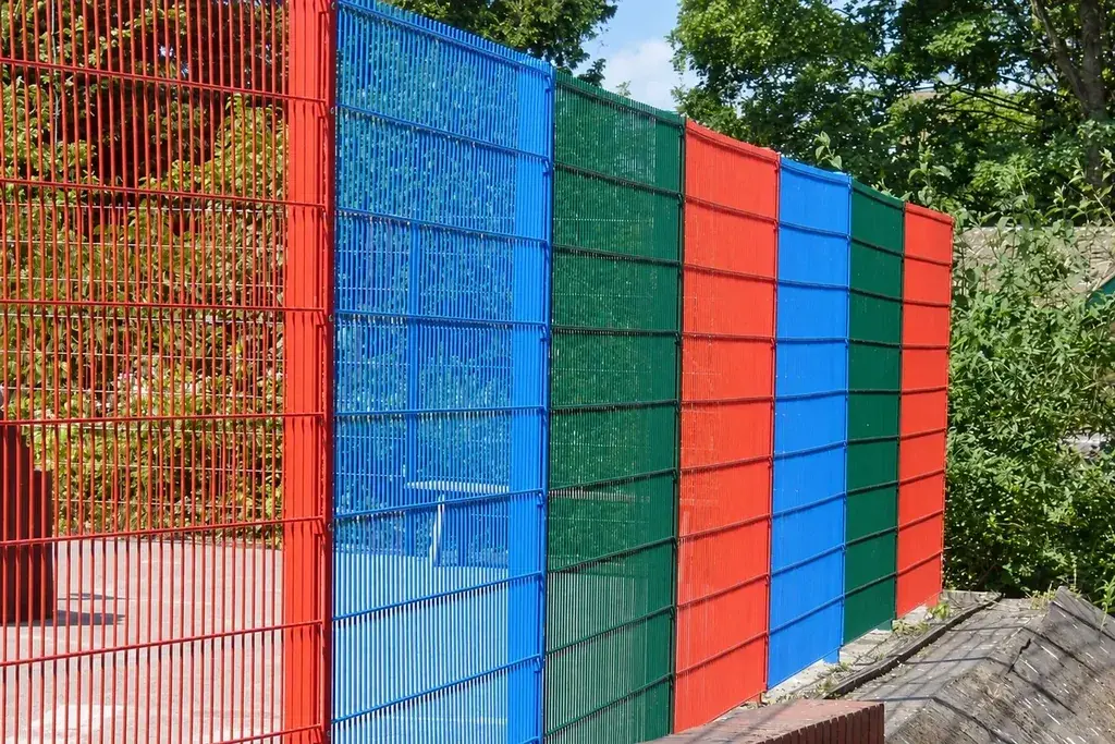
Measure overall height and width using defined references. Record aperture, wire dimensions, flat or profiled form, bend locations and edge projections. Photograph the post connection from the front and side.
For a replacement twin-wire panel, note both horizontal wires and the vertical wire. For a profiled panel, a matching number of bends is insufficient if their depth or locations differ.
Retain any original code or drawing, but compare it with the actual installed detail. Earlier site alterations may mean the catalogue description no longer captures the interface.
Check the bay with a dimensional example
Suppose an undamaged reference bay has 2,500 mm between post centres, with each post 60 mm wide along the fence line. The clear distance between post faces is:
2,500 − 30 − 30 = 2,440 mm.
If the approved detail uses 15 mm from each panel edge to its adjacent post face, the panel width is:
2,440 − 15 − 15 = 2,410 mm.
Now suppose the damaged bay measures 2,490 mm between those same centre references. Its equivalent clear face distance is 2,430 mm, ten millimetres less than the undamaged reference.
Do not immediately order a panel ten millimetres shorter. Determine whether the difference is an original setting-out condition, a measurement error or displacement caused by the damage.
These numbers are hypothetical geometry, not recommended installation clearances or acceptable post movement.
Decide which components belong in the repair
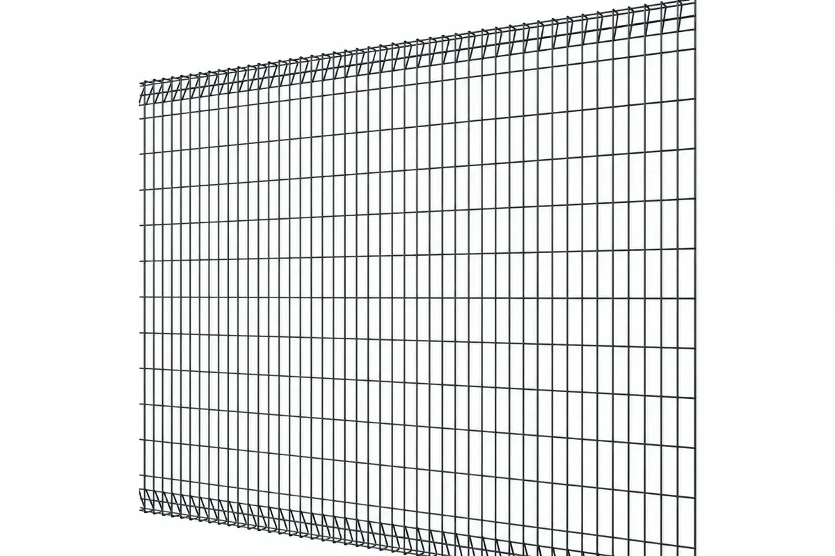
Classify parts as reusable after assessment, replacement required, or awaiting a decision. Include fasteners and small fittings, not only panels.
Permanent anti-tamper fasteners may need replacement after authorised removal. A distorted clip should not be returned to service simply because it can be tightened. Existing coating damage at contact points may require a defined treatment.
The clamp/bar comparison and fastener article help identify these dependencies.
If the original panel is unavailable, compare the proposed alternative at every interface. A change in panel form may require revised clips, posts or other design approval. It should remain a visible substitution, not be hidden inside a replacement part code.
Plan the sequence around support and continuity
A practical planning sequence is:
- Identify the affected run and confirm the approved repair scope.
- Arrange temporary boundary and access controls where required.
- Prepare compatible replacement parts, tools and handling resources.
- Follow the approved method for releasing the affected connections.
- Examine previously concealed contact areas before installing the replacement.
- Assemble to the specified joint instructions and complete the required checks.
- Restore the boundary only after the responsible team accepts the work.
Where another panel shares the connection, the method must support and control that panel too. Do not infer the safe sequence from the order in which bolts happen to be accessible.
Recheck more than the new panel's appearance
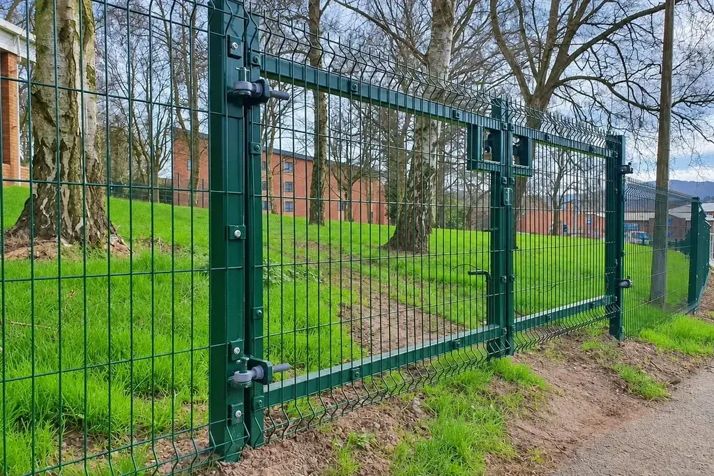
After assembly, verify the intended panel seating, edge capture, fixings, orientation, bottom detail and any adjacent gate interface. Check that the repair has not created an exposed projection or an unintended gap.
Record the new panel and fitting references. If an approved change was made, update the installed drawing or maintenance record. Otherwise the next repair may repeat the outdated specification.
Inspect the finish and complete any approved treatment for installation damage. A colour-matched touch-up is not a substitute for correcting a loose or misaligned connection.
Order compatible spares while the details are known
Once a replacement has been identified and approved, retain its dimensions and connection record. Consider spare parts based on the site's repair needs and the availability of specialised components.
For example, one spare panel without the matching permanent fasteners may not form a usable repair kit. The distributor spare-parts method shows how to group compatible items.
The completed repair record should explain what was damaged, what was assessed, which parts changed and which checks closed the work. That makes the replacement traceable and gives the next team a reliable starting point.