
By FencingWise Editorial Team · Updated 17 September 2026.
Measure across the opening, not along the diamond

Chain link openings look like diamonds when the fabric is installed. The familiar mesh size is measured as the shortest clear distance between parallel wire surfaces, not from the upper corner to the lower corner.
The CLFMI product manual, terms and wire tables documents this convention. It also gives the following wire references in its US chain link context:
| Gauge reference in that manual | Nominal diameter |
|---|---|
| 6 | 4.88 mm |
| 9 | 3.76 mm |
| 11 | 3.05 mm |
| 12 | 2.67 mm |
These values describe the cited convention; gauge numbers from other systems must not be substituted without checking. A smaller number here represents a larger nominal wire diameter.
The manual also distinguishes polymer-coated wire's core gauge from its finished coated diameter. That distinction should stay visible on your specification, particularly when comparing galvanized and polymer-coated fabric.
Use a repeatable measurement sequence
First identify the sample and orient it as shown on the supplier's drawing. A loose, distorted piece can give a misleading opening measurement. The agreed inspection method should describe how the fabric is supported and positioned for measurement.
Then measure across several identified openings, keeping the measuring direction consistent. An example record might identify the first, middle and last accessible positions in a sample section. Do not measure one diamond across parallel sides and the next along a diagonal.
Record the raw readings before calculating an average. If acceptance applies to each opening, an average cannot hide an individual result outside the agreed limits. The sampling plan and tolerance must come from the order or applicable specification; the act of taking three measurements does not make the sample statistically representative of a shipment.
Finally, photograph one measurement with its location reference. That allows another person to understand what the number describes.
Convert inches without adding false precision to the order
The exact conversion is 1 inch = 25.4 mm. Therefore:
- 2 inches = 50.8 mm.
- 1¾ inches = 44.45 mm.
- 1¼ inches = 31.75 mm.
A catalogue may use a rounded nominal metric name. That does not mean a product described as “50 mm” must measure exactly 50.800 mm. Distinguish a unit conversion from the manufacturer's nominal dimension and permitted tolerance.
For example, if a tender uses a 2-inch designation while a quotation says 50 mm, request the measurement basis and tolerance for the proposed fabric. Resolve the difference in the specification rather than changing the quote to 50.8 mm yourself.
Separate core wire from its coating
Assume an illustrative round wire with a 3.00 mm steel core and a uniform 0.50 mm radial polymer layer. Its theoretical finished diameter is:
3.00 + 2 × 0.50 = 4.00 mm.
The coating is counted twice because a diameter crosses both sides. This simple example is not a coating specification or a claim that actual coating is perfectly uniform.
A calliper reading of 4.00 mm over the finished wire would therefore not prove a 4.00 mm steel core. Using that outer diameter in a steel-weight calculation would overstate the steel cross-sectional area: 4² ÷ 3² = 1.78, under otherwise equal assumptions.
Record how core-wire evidence is obtained under the agreed inspection procedure. Do not strip coatings from saleable goods or improvise a destructive check without an approved method and representative sample.
Specify the top and bottom separately

A knuckled edge bends neighbouring wire ends back. A twisted edge joins projecting ends through a twist. These are identifiable edge constructions, not complete evidence of suitability for every location.
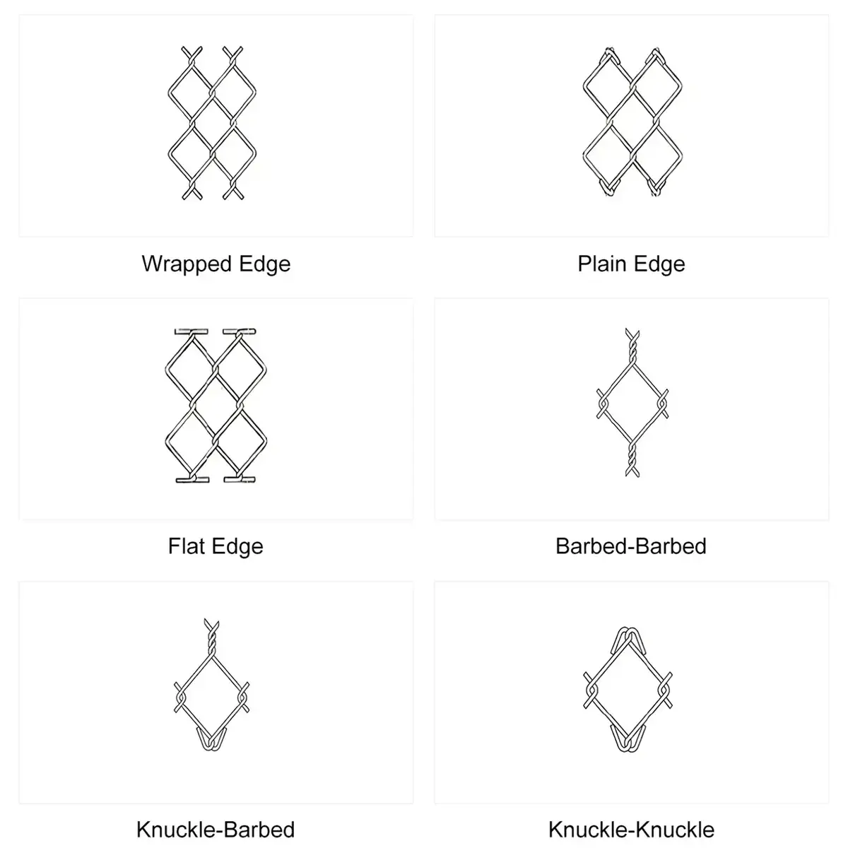
Write the two edges explicitly: for example, “top: knuckled; bottom: knuckled”, or the specific alternative required by the design. “Standard selvage” is less useful because the standard assumed by the buyer may differ from the supplier's normal product.
Pay attention to where people can contact the edge and how it meets rails, gates or adjacent surfaces. A perimeter specification for a controlled industrial boundary may not describe the appropriate detail beside an accessible pedestrian route. Let the project requirement determine the edge, then inspect against it.
Build a sample record with unambiguous fields
The following is an example format; its numbers are fictional inspection data rather than acceptance limits.
| Field | Example entry |
|---|---|
| Sample | CL-01, roll R-04 |
| Mesh basis | Shortest clear distance between parallel sides |
| Three observed openings | 50.6, 50.8, 50.7 mm |
| Wire basis | Finished diameter measured; core evidence recorded separately |
| Observed finished diameter | 4.02 mm at identified straight-wire location |
| Top / bottom | Knuckled / knuckled |
| Decision | Compare each characteristic with approved specification CL-01 Rev C |
Those measurements do not by themselves establish acceptance. The missing comparison is the approved requirement and its measurement method. Add the relevant permitted limits to the working record, then record the resulting decision.
Keep roll dimensions and system quantities separate
Fabric height and usable roll length complete the material description. They do not define post spacing, terminal fittings or the number of rolls needed for several separated runs.
Use the roll-to-system counting example after the fabric is identified. That sequence avoids a common purchasing mistake: carefully specifying wire gauge, then assuming that a roll-only price contains everything needed to install it.