
By FencingWise Editorial Team · Updated 17 September 2026.
Distinguish support components by their job
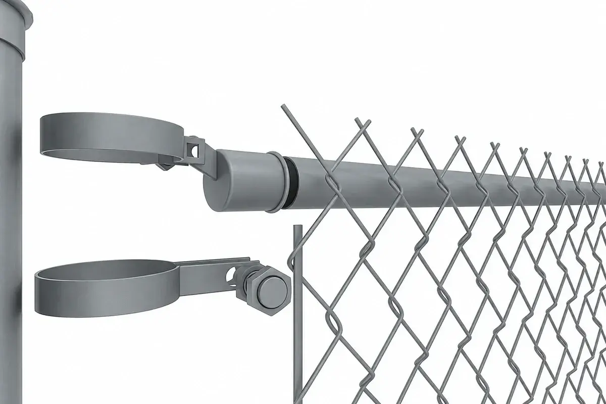
Line posts support the fence along a run. Terminal posts occur where fabric is terminated, including ends, gates and selected changes of direction or pull points. Bracing transfers the relevant forces into the supporting arrangement.
A tension bar distributes attachment along a fabric end. Tension bands connect that bar to the terminal post. Rails, tension wires and fabric ties perform different functions and should not be treated as interchangeable spare parts.
The CLFMI commercial and industrial specification guide describes these component relationships and installation provisions. Use the selected system's details and the applicable project specification for the actual spacing and support requirements.
Divide the fence into tensioning runs
Draw each independently terminated fabric run between its supporting points. Show gate openings, corners and other breaks before counting rolls.
For a simple example, a boundary has 35 m of fence, then a 5 m gate opening, then another 40 m of fence. The total boundary extent is 80 m, but the fabric length is 75 m.
There are two fabric runs and four fabric-end terminations. The gate opening does not receive another 5 m of fence fabric, and the fabric should not be assumed to continue through the gate.
A post may serve more than one function only where the design permits it. Two terminating fabric ends at a corner still need the appropriate attachment and support arrangement for both directions.
Count termination hardware from the approved detail
Assume each of the four terminations in the example uses one tension bar and six specified band assemblies.
The requirement is:
4 tension bars and 4 × 6 = 24 band assemblies.
The six-band assumption is only for this quantity example; it is not a standard spacing recommendation. The real count follows the fence height, detail and applicable specification.
Keep braces, rails, wires and ties on separate lines. A complete fabric attachment count does not establish that the terminal support is complete.
Complete the supports before pulling the fabric
Install terminal and line posts using the approved foundation or anchorage arrangement. Establish their alignment, elevation and permitted loading condition.
Fit the designed bracing and framework in the specified sequence. Check the direction of each brace and the way it connects to the terminal and adjacent support.
If a terminal post begins to move while tension is applied, stop and investigate. More pull does not create a stronger foundation. Do not use nearby vehicles, trees or unverified structures as convenient substitutes for the designed support or tensioning equipment.
Keep people clear of stored-energy hazards during pulling and adjustment. Use equipment and methods suitable for the work, with competent supervision.
Attach and tension one defined run
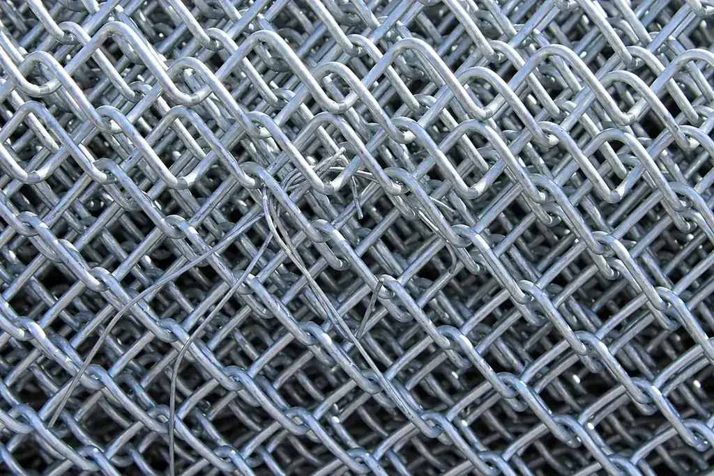
A practical controlled sequence is:
- Unroll and orient the fabric according to the approved selvage and side detail.
- Prepare the first termination with the specified bar and fittings.
- Support the fabric to avoid damage and unwanted twisting.
- Apply the prescribed tensioning method toward the next terminal.
- Form the final termination at the required position.
- Complete intermediate attachment to posts, rails or wires as specified.
- Check the run's alignment, bottom condition and end-support stability.
The exact order and attachment details can vary by system. Do not impose a universal pull force or tension-wire torque without the relevant instructions.
A taut appearance alone is not an acceptance test. Excessive tension can distort mesh, move supports or damage coating.
Check the mesh and support geometry after tensioning
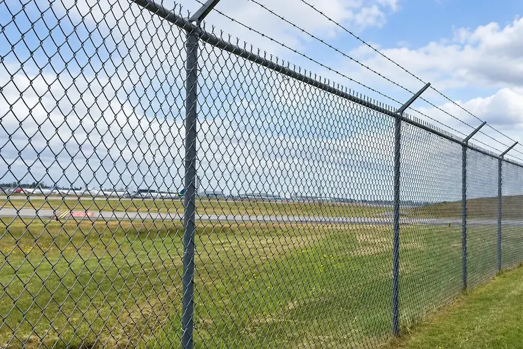
Look for uneven diamonds, local kinks, loose areas and altered terminal alignment. Compare the top and bottom lines with the intended profile.
For an illustrative fabric height of 1,800 mm, a local installed height measured as 1,740 mm represents a 60 mm reduction. That observation deserves investigation into fabric deformation, orientation or measurement convention; it should not automatically be corrected by pulling harder.
Check the bottom along depressions as well as at posts. For slopes, use the specified method of following the grade or forming transitions. Improvised cuts and tied scraps can produce weak or sharp local details.
Leave a record that supports future retensioning
Record run IDs, terminal locations, fabric specification and component references. Photograph end attachments and braces before vegetation or stored goods conceal them.
If a run later becomes slack, inspect supports and connections before retensioning. Settlement, impact or a failed attachment can cause the same visible symptom as relaxed fabric.
Keep replacement fabric compatible in mesh, wire size, coating and selvage. The chain-link measurement guide explains those identities. A matching-looking roll can still behave differently if its wire core or mesh construction changes.