
By FencingWise Editorial Team · Updated 17 September 2026.
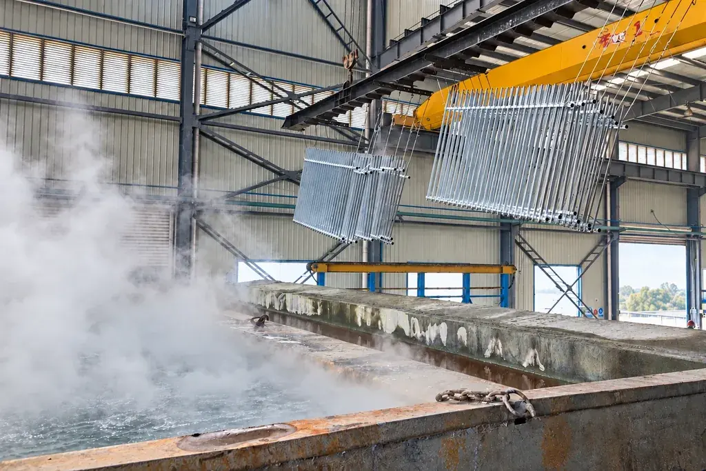
Identify what was galvanized and when
Separate fabricated articles from wire coated before panel manufacture. Record the applicable standard, product category, steel thickness and any additional order requirement.
For fabricated steel articles that are not centrifuged, the Galvanizers Association's EN ISO 1461 summary gives the following minimum local and mean coating thicknesses:
| Steel thickness category | Local minimum | Mean minimum |
|---|---|---|
| 1.5 mm to 3 mm inclusive | 45 µm | 55 µm |
| Over 3 mm up to 6 mm | 55 µm | 70 µm |
| Over 6 mm | 70 µm | 85 µm |
Use the actual standard and agreed inspection arrangement for acceptance. The table is not a specification for all fence wire or centrifuged threaded parts.
The relevant steel thickness is the thickness of the material being galvanized, not the outside dimension of a hollow post. A 60 mm square tube is not “over 6 mm steel” merely because its outside width exceeds 6 mm.
Distinguish a reading, a local result and a mean
Inspection methods define how individual readings are collected within reference areas and how the resulting values are assessed. A single instrument reading should not automatically be labelled the standard's “local thickness”.
Set up the record so raw readings, reference-area results and the applicable overall mean remain visible. Retain the sampling basis and component identification.
This matters because a favourable overall mean can conceal a deficient local area. It also prevents a low isolated instrument reading being interpreted without the required measurement procedure.
Work through a local-versus-mean decision
Consider a hypothetical 4 mm thick fabricated steel component in the non-centrifuged category above. Assume the applicable inspection procedure has already been followed and gives three valid local-area results of:
54 µm, 75 µm and 81 µm.
For a simplified equal-weight illustration, their mean is:
(54 + 75 + 81) ÷ 3 = 70 µm.
The mean meets the category's 70 µm minimum, but the 54 µm local result is below 55 µm. The component therefore cannot be accepted merely by quoting the mean.
This example does not prescribe three reference areas for every article. Sampling extent and result aggregation must follow the applicable method. It demonstrates why both requirements need to be checked.
Use a method that suits the surface
Before measurement, verify the gauge using the appropriate procedure and reference materials. Probe geometry, surface curvature, roughness and proximity to edges can affect the result.
A method suitable for a broad post face may not be suitable for a small wire. Establish how the wire coating is to be assessed under its applicable specification rather than forcing a large probe onto an unsuitable surface.
Identify repair areas and other special surfaces separately. Do not silently mix their readings into the original coating results.
Separate zinc from organic layers
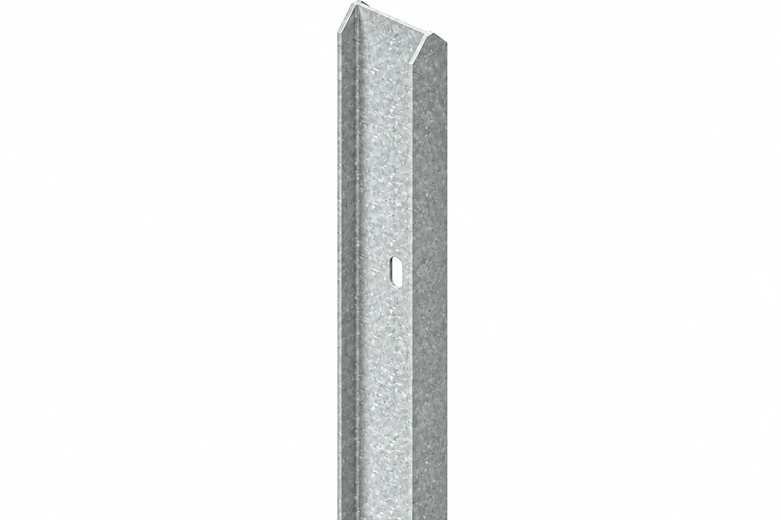
A galvanized-and-powder-coated article has more than one non-steel layer. An ordinary magnetic measurement may report a combined thickness rather than the zinc layer alone.
For a duplex coating, check whether the instrument can distinguish the paint and zinc layers. The instrument, measurement method and operating mode must suit the actual coating system.
For an illustrative assembly containing 65 µm zinc plus 85 µm organic coating, the total is 150 µm. A 150 µm total reading is not evidence of 150 µm zinc. Record layer-specific results or clearly state the limitation of the available measurement.
If readings are taken before and after powder coating, trace the locations and account for the measurement procedure. Subtracting unrelated average values can create an apparently precise but unreliable layer estimate.
Understand the relationship between mass and thickness
For a uniform layer, mass per area is density multiplied by thickness. Using 7,140 kg/m³ as an approximate density for pure zinc (the IFRC/ICRC gauge guidance uses the corresponding 7.14 conversion), an illustrative 70 µm layer corresponds to:
7,140 × 70 × 10⁻⁶ = 0.4998 kg/m², or 499.8 g/m².
Across 4 m² of actual coated surface, that is approximately 2.00 kg. The surface area is not necessarily the panel's rectangular face area; wires and hollow sections have their own coated geometry.
This theoretical conversion does not replace specified coating-mass tests or a standard's conversion convention. Alloy layers, actual density and measurement definitions can differ.
Keep acceptance evidence component-specific
The final record should identify the component type, batch, galvanizing route, governing requirement, method, individual measurements, calculated results and disposition. Link repairs and retests to the original record.
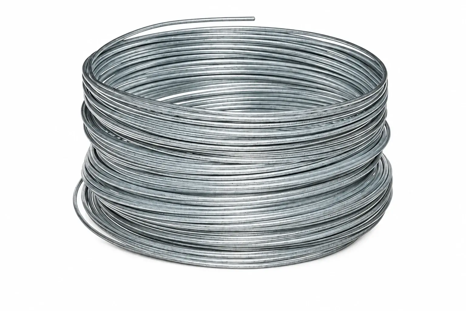
For mixed fence shipments, separate panel-wire evidence from fabricated-post and fastener evidence. The galvanizing-process comparison explains why those routes should not be merged into one unexplained “galvanized” claim.