
Compare fixed and removable feet
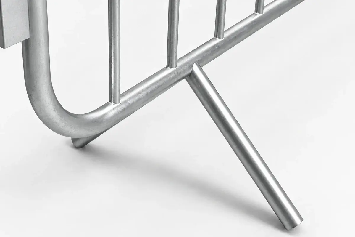
Fixed feet remain with the barrier, reducing the number of loose items to reconcile. They can also enlarge the stack footprint or complicate handling. Removable feet may pack separately and offer a different deployment arrangement, but their type, retention and quantity must stay associated with the correct barrier.
Neither arrangement is universally better. Ground, handling, storage and the intended barrier duty determine which complete system is appropriate. Avoid choosing a foot solely because it looks less intrusive in a photograph.
| Detail | Fixed foot | Removable foot |
|---|---|---|
| Stock control | Foot remains attached | Loose component needs identification |
| Transport | Projection affects stack geometry | Separate packing and retention needed |
| Damage assessment | Examine attachment and foot together | Examine socket, foot and locking detail |
| Replacement | May involve the whole frame or approved repair | Requires the exact compatible foot |
Measure the actual clear route

In an illustrative 2.4 m corridor, feet project 0.18 m inward on one side and 0.22 m on the other. The remaining clear width is 2.4 − 0.18 − 0.22 = 2.0 m. Signs, cables or uneven alignment could reduce it further.
This calculation is a layout measurement, not a statement of acceptable capacity or accessibility. Give the actual clear width to the responsible event planner. HSE's barrier guidance considers ground, layout and use together. HSE: barrier selection.
If the chosen feet do not fit the approved route, revise the equipment or layout. Turning or removing a foot without the system's approval can invalidate its intended arrangement.
Check hook engagement at every change of direction
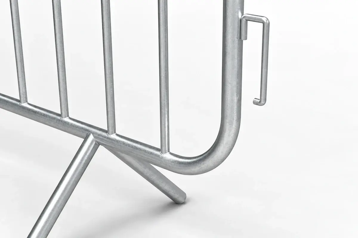
Record the mating hook and receiver dimensions, connection direction and permitted articulation. Test the junction on representative ground. A hook can appear engaged from one side while sitting incorrectly when the ground changes level.
Corners and short returns deserve a trial assembly. Do not assume the same connection angle is available in both directions or that barriers from two suppliers can be mixed because their heights match.
Follow the manufacturer's deployment and removal method. Do not improvise a lift or twist sequence around the public to overcome a mismatched connection.
Reconcile a removable-foot package
Suppose an illustrative system uses two dedicated feet per barrier. A delivery of 60 barriers needs 120 installed feet under that arrangement. If the agreed spare provision is four additional feet, the packing list should show 120 installed plus four spare, or 124 total.
If 118 serviceable feet arrive, the shortage against the installed requirement is two; the shortage against the full order is six. Keeping those two figures separate helps the team understand both immediate usability and the missing spare provision.
This example does not apply to systems that share feet or use another support pattern. Count from the actual product detail.
Check compatibility before mixing suppliers
Place representative units from the proposed families together using their specified deployment method. Examine hook engagement, relative height, permitted articulation and support position. A junction that can be connected on a flat workshop floor may behave differently across the site's actual level change.
If compatibility is not established, keep the families in separate approved lines rather than improvising a connector. A strap or tie that closes a visible gap does not demonstrate the intended connection duty. The event layout and component schedule should identify where each family begins and ends.
For returning equipment, use labels or controlled storage locations that remain readable after repeated handling. This is especially useful where removable feet appear similar. The issue record should allow a crew to select the approved combination without relying on memory or guessing from the colour of a weathered component. Record accepted substitutions so later dispatches reproduce the same arrangement.
Inspect, identify and retain compatibility information
At receipt, inspect bent frames, damaged feet, sharp edges and connection condition. Trial-assemble representative units with the actual supplied components and retain the reference drawing. Separate damaged or unidentified parts so they cannot be issued inadvertently.
For repeated use, label compatible families clearly and record approved substitutions. A mixed stockyard can produce a visually continuous line with inconsistent connections unless the issue process controls component identity.
Use crowd control barriers for the product scope and barrier versus security-fence duties before assigning the equipment to a crowd-management function.