
Separate the physical boundary from detection
NPSA describes different perimeter detection arrangements in its PIDS guidance. Detection, verification and response are distinct functions; a sensor does not turn an unspecified fence into a rated security system.
The procurement package should name the specialist responsible for the detection design. FencingWise’s supply description should remain limited to the agreed fencing and component scope, rather than implying that electronics, control-room integration or operational response are automatically included.
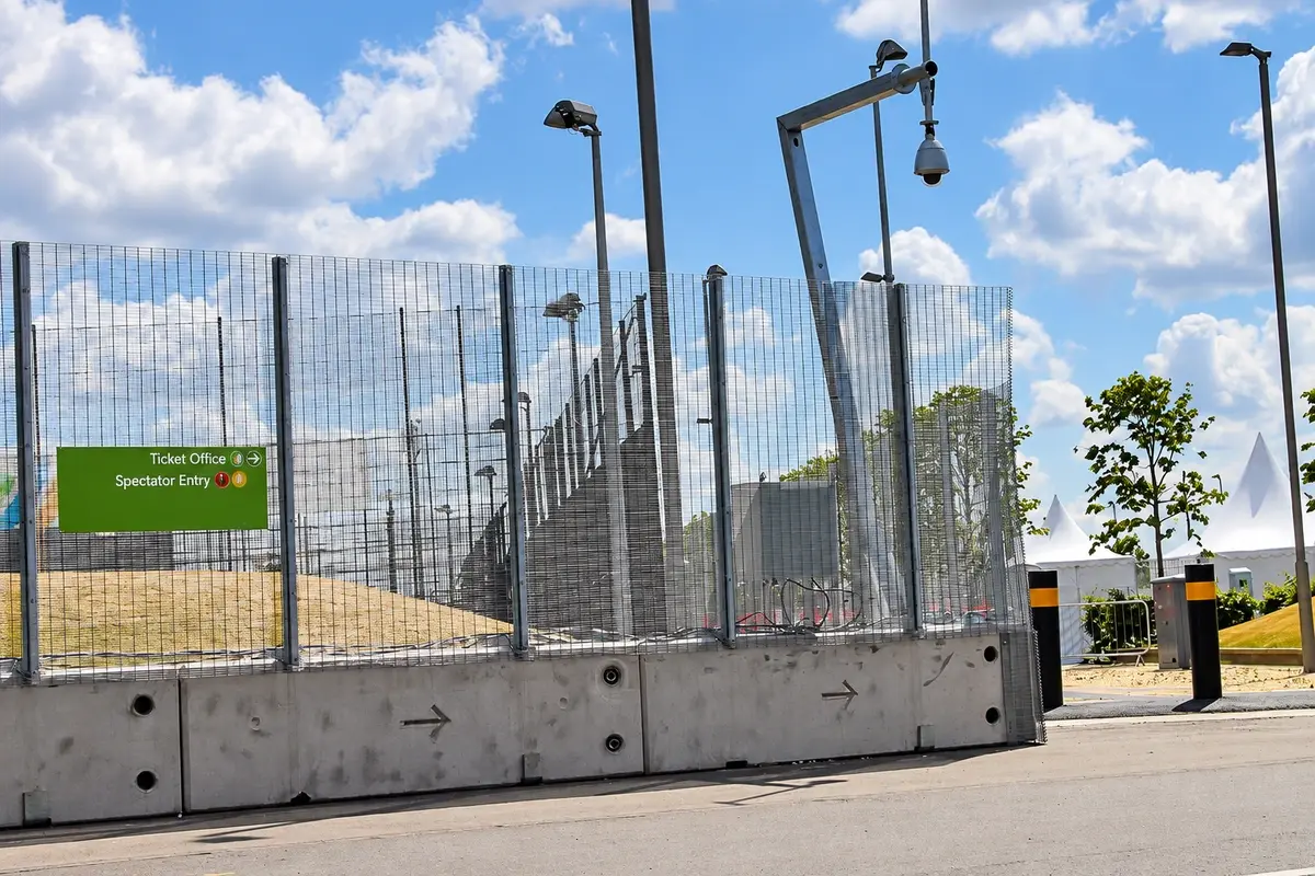
Write the interface table before installation
| Interface | Information exchanged | Responsible decision |
|---|---|---|
| Sensor attachment | Device, attachment method and relevant loads | Fence designer and system specialist |
| Cable route | Supports, movement joints and gate transitions | Integrator with the fence installation team |
| Electrical services | Power and applicable protection requirements | Responsible electrical specialist |
| Operational zones | Identification and system mapping | Security system designer |
| Acceptance | Agreed tests, records and unresolved issues | Client and commissioning parties |
Give the table named owners and document references. “By others” without identifying the other party is an unresolved interface, not a completed exclusion.
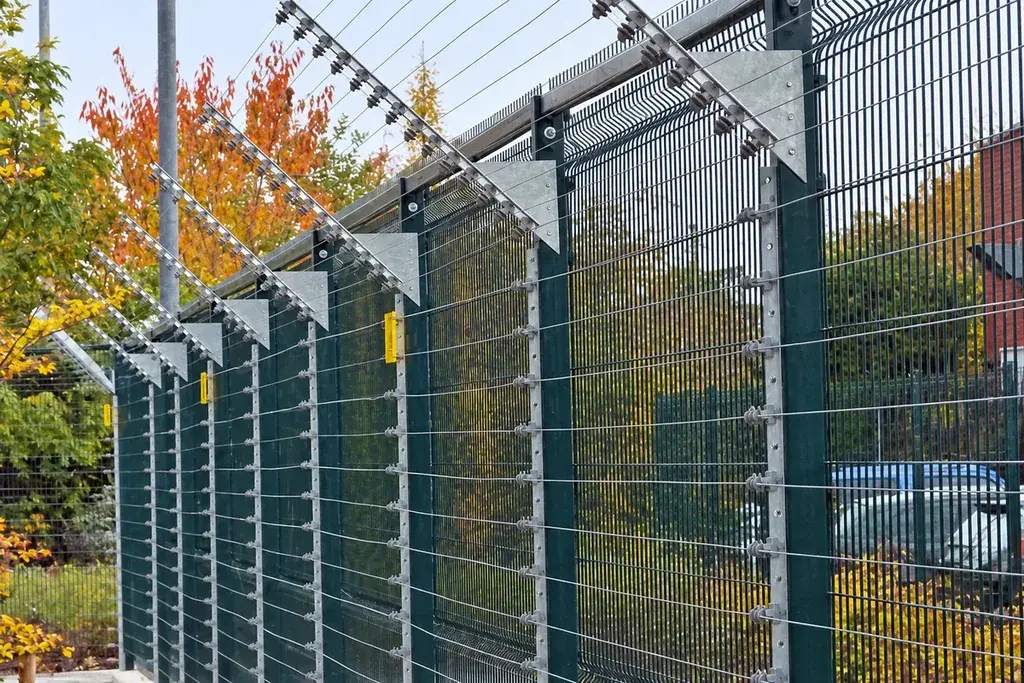
Use consistent location identifiers
For illustration, a 600 m route might be divided into six 100 m management segments. Those segments can help align inspection and maintenance records. They are not a recommended detection-zone length; the actual detection design may use a different arrangement.
Map both systems to a common drawing so an authorised maintenance team can identify the relevant run and equipment without guessing. Keep sensitive operational details in controlled site documentation rather than on public product pages.
Coordinate changes to the fence
Panels, connections, gates and adjacent additions can affect the mounted arrangement. Require review before adding brackets or replacing a panel with a different construction. Follow the approved method for removing and reinstating sensors during repair.
Likewise, a proposed electronic upgrade may introduce different attachment or cable requirements. Return those to the fence designer rather than treating spare space on a post as evidence of structural capacity.
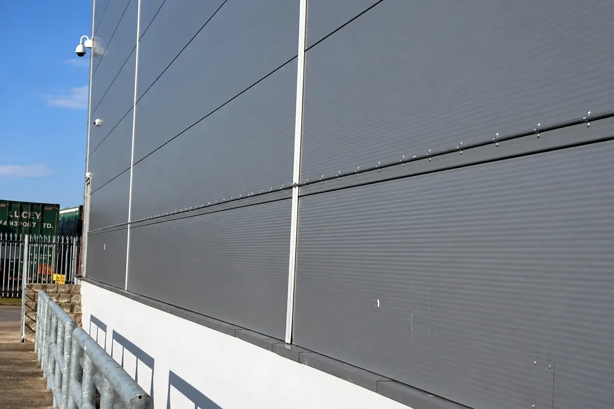
Agree a combined handover
The fence inspection records should identify the accepted physical assembly. The system specialist should provide the applicable commissioning and operational records. Cross-reference the two packages and record outstanding interfaces before the client accepts the combined installation.
After later repairs, recheck the affected functions through the approved procedure. Replacing a panel and restoring a cable’s appearance are not equivalent to confirming system operation.
For future equipment provisions, the conduit and bracket planning method explains how to record physical provisions without promising unspecified future compatibility.