
Separate the steel detail from the substrate
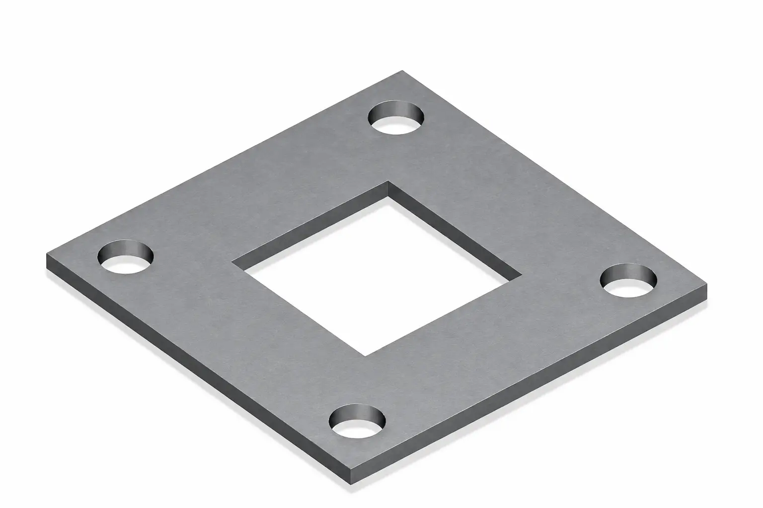
The steel drawing should identify plate dimensions, thickness, post position, weld detail and holes or slots. The supporting-structure information should identify material, dimensions, condition, reinforcement where relevant and the location of free edges. The anchor specification connects those two sets of information.
Do not infer concrete capacity from the visible width of a kerb or slab. Nor should a hole that accepts an M16 bolt be treated as an approved M16 anchorage design. Selection depends on the actual loads, substrate and installation conditions.
Anchor design and installation documents are product-specific. Use the current documents and approvals for the actual selected fixing, together with the responsible designer's assessment; a generic online table is not a project design.
Label the two different edge distances
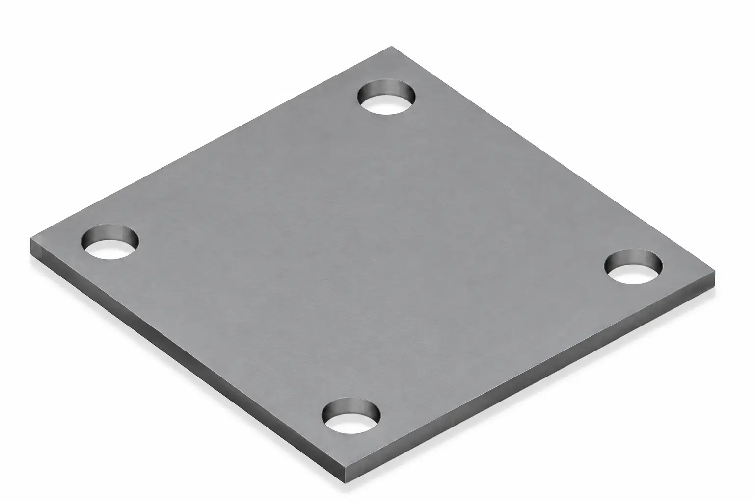
Consider a hypothetical square plate 200 × 200 mm with a centred 140 × 140 mm hole pattern. Each hole centre is (200 − 140) ÷ 2 = 30 mm from the corresponding plate edge.
Now place the plate centrally on a 300 mm-wide concrete support, with the pattern aligned to its edges. The nearest hole centres are (300 − 140) ÷ 2 = 80 mm from the concrete edges. Thirty millimetres and eighty millimetres are both correct, but they refer to different materials.
If the plate is offset 25 mm towards one concrete edge, that side's anchor-centre distance becomes 55 mm and the opposite side becomes 105 mm. The steel plate geometry has not changed. Whether either arrangement is acceptable requires the actual anchor and structural design.
| Example measurement | Centred plate | Plate offset 25 mm |
|---|---|---|
| Hole centre to plate edge | 30 mm | 30 mm |
| Nearest anchor centre to concrete edge | 80 mm | 55 mm |
| Opposite anchor centre to concrete edge | 80 mm | 105 mm |
These are geometry examples, not minimum permitted edge distances. They show why a plate-only sketch cannot establish anchorage suitability.
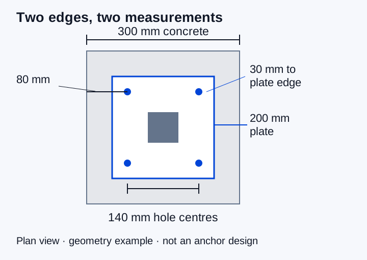
Centred plan example only. The 30 mm plate-edge distance is not the 80 mm concrete-edge distance; neither is an approved design minimum.
Define the whole anchor assembly
Record the exact anchor product, material, diameter, required embedment, hole preparation, installation procedure and the applicable design reference. Identify washers, nuts and any stand-off or grout arrangement specified by the designer. Keep temporary positioning separate from the final load-bearing condition.
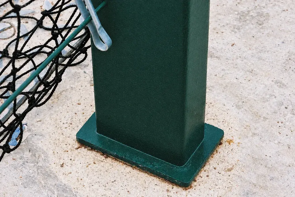
Slots may help align a connection, but their direction and permitted use must be defined. A slot can change how forces transfer or require a particular washer arrangement. Do not enlarge holes or substitute a fixing on site simply because it makes the post easier to position.
Coating also affects assembly. Threads, bearing surfaces and post alignment should remain usable after finishing, while the corrosion protection of the complete fixing detail is preserved.
Review the interfaces before manufacture
- Match the post reference and orientation to the fence elevation.
- Confirm plate dimensions and hole coordinates from a common datum.
- Overlay the plate on the actual supporting-structure geometry.
- Check the anchor specification and approved installation conditions.
- Identify conflicts with reinforcement, services or nearby connections through the project's survey and design process.
- Release the coordinated drawing and retain its revision with the purchase order.
This review prevents a common split responsibility: the steel supplier assumes the anchors will fit, while the anchor installer assumes the steel layout has already been designed.
Inspect received parts against the approved drawing
Check plate identity, dimensions, hole locations, post orientation, visible weld condition and coating. Trial-fit the intended hardware where agreed, without treating trial fit as a capacity test. Record a nonconformity if the hole pattern or finish prevents the approved assembly.
The site installer also needs the actual substrate and installation checks described in the base-plated post pre-installation guide. A correct fabricated plate cannot compensate for unsuitable concrete, incorrect embedment or an unapproved foundation detail.
Keep the accepted plate, anchor and substrate references together in the handover file. A future replacement then starts from the complete connection rather than an isolated plate measurement.