
Define the angle convention
State whether the arm angle is measured from horizontal or vertical. A drawing marked 30° without that reference can produce two different assemblies. Include an elevation and a section showing which side of the boundary the arm projects towards.
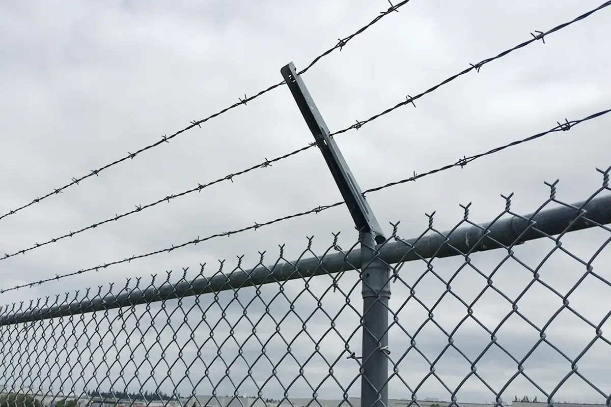
For an illustrative straight arm 300 mm long at 45° above horizontal, horizontal projection and vertical rise are both 300 × cos(45°), approximately 212 mm. For the same length at 30° above horizontal, projection is about 260 mm and rise is 150 mm.
These are geometric examples, not approved arm dimensions. The finished topping envelope can extend beyond the arm itself and needs to be shown separately.
Identify the post connection
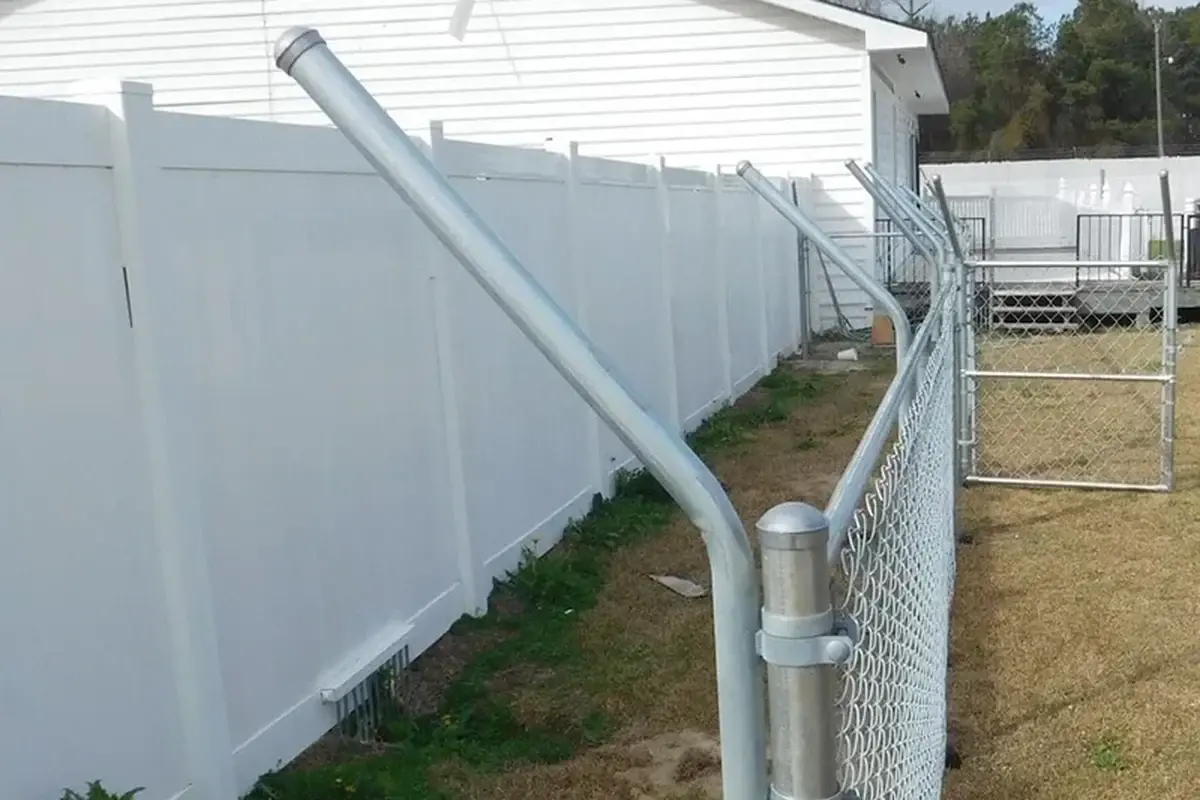
An arm may be integral with a post or attached by a specified bracket. Identify the post section, wall thickness, hole pattern and the finished connection surfaces. An arm that fits over the outside of one post may not fit a post with the same nominal description but a different profile or finish.
| Drawing field | Required distinction |
|---|---|
| Arm length | Along the member, not its horizontal projection |
| Angle | Reference axis and direction |
| Connection | Integral, bolted or other approved detail |
| Handedness | Left, right, inward or outward as explicitly drawn |
| Topping attachment | Identified interface and permitted arrangement |
The post and foundation assessment must include the completed arrangement. A geometrically compatible bracket does not demonstrate capacity for the revised loading.
Count by support duty
Suppose an illustrative open run has 21 post positions. If the approved detail calls for an arm at every position, that is 21 arms. If the two terminal positions use special assemblies, the schedule becomes 19 line arms plus two terminal assemblies, rather than 21 interchangeable pieces.
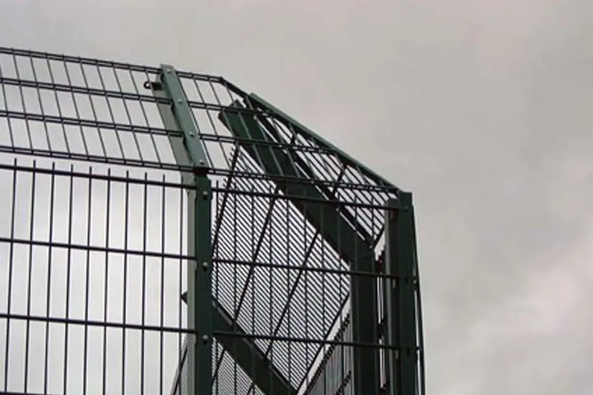
Add corners and gate interfaces by their own references. At a corner, the topping changes direction and may need a different connection. At a gate, moving and fixed parts must remain compatible throughout operation.
If each of the 19 line arms has two specified fasteners, that contributes 38 fasteners. It says nothing about the fastener requirement for the two special ends, which must be counted from their drawings.
Review the occupied space
Show the complete envelope in relation to the property boundary, public routes, vegetation and maintenance access. An inward arm should not obstruct a gate's path, lighting access or a planned maintenance operation. An outward projection needs the appropriate site and permission review rather than an assumption that the fence line authorises it.
Toppings involving sharp components need a suitable installation and maintenance method by competent personnel. Do not turn a procurement geometry sketch into an instruction for handling or tensioning hazardous materials.
Check handed parts against a fixed viewpoint
Define inward and outward on the site drawing and specify the viewpoint used for left and right. A packing label stating left arm is ambiguous if the factory and installer look from opposite sides of the boundary. Use a small plan symbol or reference arrow that remains consistent across drawings and labels.
At a corner, check whether the same arm can be used without changing the topping envelope or connection. A standard line component should not be rotated into a special position simply because its bolt holes align. Review the complete junction and identify any dedicated part.
For receiving inspection, compare a representative finished arm with its intended post and drawing orientation. Keep the special-part labels attached until installation. This avoids discovering an orientation error after the post is installed and makes the replacement reference clear if an arm is damaged during later maintenance.
Freeze the interface before ordering
Approve a representative finished connection, including the actual post and specified hardware. Mark the drawing revision and orientation on the packing schedule. Separate special arms so the installer can identify them without trial fitting at height.
The replacement record should retain arm geometry and fastener identity, not merely the phrase cranked bracket. For the material choice above the arm, see barbed wire versus razor wire. For the support itself, fence posts provides the product context. The completed design must resolve the connection, projection and site duty together.