
By FencingWise Editorial Team · Updated 17 September 2026.
Collect the dimensions that a weight label leaves out
Record the complete leaf mass, its centre-of-gravity distance from the hinge axis, the vertical distance between effective hinge centres and the required opening angle. Include locks, closers, decorative plates and other equipment attached to the leaf.
Also identify the post and frame sections, their wall thicknesses and the mounting method. A suitable hinge body cannot compensate for an inadequate fixing into a thin wall or a poorly supported gate post.
Hinge selection must account for gate weight, width, mounting geometry and the number of hinges. Check the documented limits of the selected hinge set; a capacity stated for one arrangement does not apply to arbitrary hinges or gates.
Calculate the gravity moment
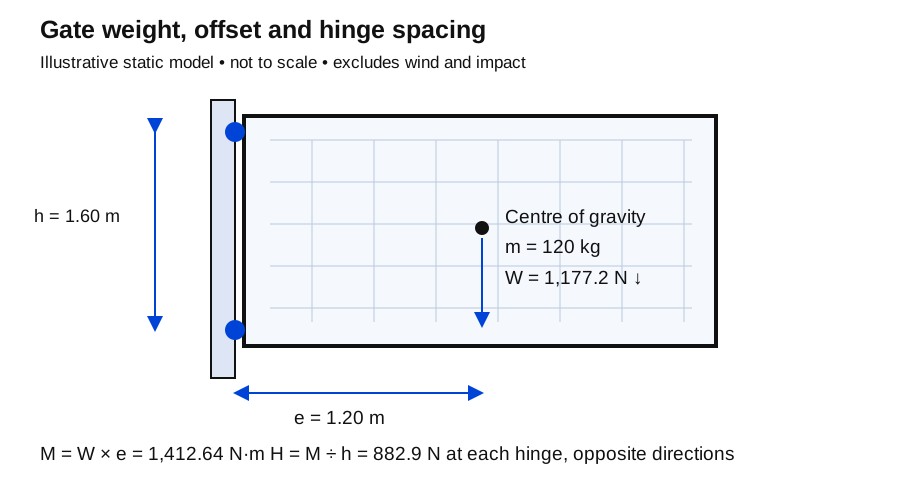
For an illustrative leaf:
- Mass, m = 120 kg.
- Centre of gravity, e = 1.20 m from the hinge axis.
- Effective vertical hinge spacing, h = 1.60 m.
- Gravitational acceleration used, g = 9.81 m/s².
The leaf weight is W = m × g = 1,177.2 N.
Its gravity moment about the hinge support is:
M = W × e = 1,412.64 N·m.
This is a static calculation for the specified centre of gravity. It excludes wind, impact, closer forces, misuse and design factors. It helps explain the loading; it does not size the hinge or certify the gate.
See what hinge spacing changes
In a simplified two-hinge model, opposite horizontal reactions form a couple that resists the gravity moment:
Horizontal reaction magnitude, H = M ÷ h.
For the example, 1,412.64 ÷ 1.60 = 882.9 N at each of the two hinge positions, acting in opposite directions.
If spacing falls to 0.80 m, the magnitude becomes 1,765.8 N. The mass has not changed, yet this reaction doubles. Similarly, moving the centre of gravity farther from the axis increases the moment.
Do not assume each hinge carries exactly half the vertical weight. Actual load sharing depends on hinge type, adjustment, tolerances and stiffness. Adding a third hinge does not automatically divide every load into thirds.
Use the manufacturer's selection information
| Selection item | What to compare | Common error to avoid |
|---|---|---|
| Weight rating | Complete leaf mass and stated rating conditions | Using mesh mass alone |
| Width limit | Hinge-axis-to-leaf geometry | Checking kilograms but ignoring width |
| Hinge spacing | Actual effective centres | Measuring overall post height |
| Opening angle | Required travel and nearby obstructions | Assuming every hinge opens 180 degrees |
| Mounting | Approved bolts, welds or inserts and substrate | Substituting an unverified fixing |
| Duty and environment | Use frequency, corrosion exposure and maintenance | Selecting only by appearance |
Read any load diagram together with its notes. The allowable configuration may depend on a relationship between leaf width and hinge spacing. A rating for a pair should not be interpreted as the capacity of each individual hinge.
Where the selection information does not cover the actual geometry, obtain a supported selection from the hinge or gate designer instead of extrapolating from a smaller leaf.
Reserve adjustment for alignment
An adjustable hinge is useful for setting gaps and correcting permitted installation variation. Its adjustment range is not permission to compensate for a misplaced post by any amount necessary.
Measure the required correction before ordering. If the example gate needs a 12 mm lateral movement and the selected arrangement provides only 8 mm of usable adjustment in that direction from its installed position, 4 mm remains unresolved. Moving the hinge to its mechanical limit may also reduce the intended engagement or clearance.
Show the initial setting and available adjustment on the installation record. This preserves useful movement for future alignment without concealing an incorrect opening.
Include retention and service access
Consider what keeps the leaf attached if a hinge component loosens or fails. The required retention arrangement belongs to the complete gate design. It should not be invented on site using a convenient chain or spare bolt.
Allow access for inspection, lubrication where specified and replacement. Protective caps or anti-tamper features must be compatible with that maintenance method.
Before final release, operate the supported and correctly assembled leaf through its intended travel, check clearances and follow the supplier's commissioning instructions. Record the hinge model and mounting components so replacements can be matched later.
If the gate already sags, use the sagging and binding diagnosis before ordering larger hinges. Post movement, frame distortion or a rising threshold may be the actual cause.