Set the reference faces on the drawing
Identify the fence-facing side, post centreline, plate centre and the origin used for hole coordinates. Show any offset post position and distinguish a left-hand assembly from its right-hand counterpart. Put those references on the cutting and assembly information used at the workshop.
For hollow posts, record the outside section, wall thickness, length and end treatment. A single dimension such as 80 mm does not fully describe a square hollow section. Material and tolerances must remain attached to the component reference.
If a post carries gate hardware, topping arms or equipment, include the approved attachment positions and orientation. Do not drill an additional hole or weld a bracket after finishing without reviewing the changed detail and its protection.
Work through a four-hole coordinate example
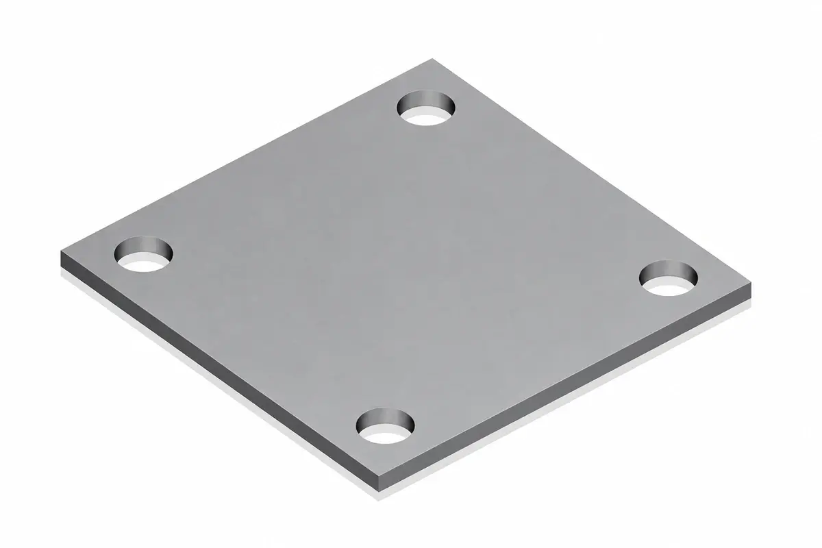
Assume an illustrative plate 240 mm square with a centred 160 mm square hole pattern. Taking the lower-left plate corner as the origin, the four hole centres are (40,40), (200,40), (200,200) and (40,200), all in millimetres.
The hole centres lie 40 mm from the corresponding plate edges. Adjacent centres are 160 mm apart; the diagonal between opposite hole centres is √(160² + 160²) = 226.27 mm.
| Hole | X coordinate | Y coordinate |
|---|---|---|
| H1 | 40 mm | 40 mm |
| H2 | 200 mm | 40 mm |
| H3 | 200 mm | 200 mm |
| H4 | 40 mm | 200 mm |
These are fabrication geometry assumptions, not an approved anchorage layout. The supporting concrete, loads and anchor design may require entirely different dimensions. The base plate and anchor guide explains that separate structural interface.
Inspect before welding fixes the orientation
Place the components in the intended fixture and compare them with the drawing. Check post position, rotational orientation, hole pattern and access to the future fasteners. A weld can make a simple alignment error expensive to correct, so the first assembly deserves an independent dimensional review.
The production procedure should control joint preparation, welding and distortion for the actual materials. Welding symbols and required joint dimensions need to be read from the approved drawing, not inferred from a photograph of another post.
Check whether a nut, washer or installation tool can reach every anchor position after the post is attached. A geometrically correct hole can be unusable if the post or a stiffener blocks access.

Keep the coating route compatible with fabrication
Hollow and overlapping details intended for hot-dip galvanising require suitable venting and drainage coordinated with the galvaniser. The Galvanizers Association's design-detailing guidance explains why these features belong in the design stage.
Do not copy a vent-hole location from an unrelated section. The galvanising arrangement, component geometry and structural requirements need to be considered together. Any fabrication change should appear on the controlled drawing before production repeats it.
After finishing, verify that holes and connection surfaces remain usable and that any required repair has been completed. Enlarging a hole to overcome coating or alignment problems is a design change, not an automatic workshop adjustment.
Separate dimensional results from acceptance
Record actual measurements at defined positions. A note reading “plate correct” provides little help if an installer later finds the pattern does not match the anchor template. Retain the instrument, method and drawing revision where the inspection plan requires them.
Suppose a measured hole centre is 201 mm rather than the nominal 200 mm. The deviation is +1 mm on that coordinate. Whether it passes depends on the specified tolerance and measurement uncertainty, not the fact that the bolt can be forced through during a trial.
For repeated parts, use the agreed sampling and control plan. Do not claim every component has been checked if the record covers only a sample.
Pack by installation identity
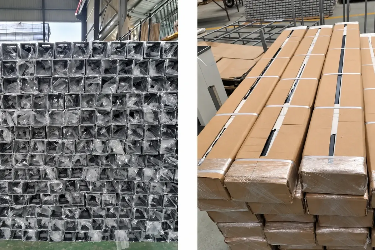
Label post types and handed assemblies so the installer can distinguish them before unpacking the whole delivery. Protect finished plates and protruding brackets against damage. Keep any matched fixing or cap references in the component schedule.
The final record should connect the material, drawing, inspection and pack identity. Posts and fixing components can then be reordered by a controlled reference rather than reconstructed from a photograph of an installed base.