
By FencingWise Editorial Team · Updated 17 September 2026.
Identify the active and inactive leaves
The active leaf normally opens first for routine passage. The inactive leaf may remain retained until a larger opening is needed. This sequence affects latch handing, lock position and the location of drop bolts.
Mark both leaves on the plan as viewed from a stated side. “Left-hand gate” is ambiguous if the supplier and installer stand on opposite sides.
For a hypothetical 4.0 m double-leaf opening with equal leaves, opening one leaf does not necessarily provide exactly 2.0 m of usable passage. The centre stop, leaf thickness and hardware projections can reduce that space. Measure the actual passage in its operating position.
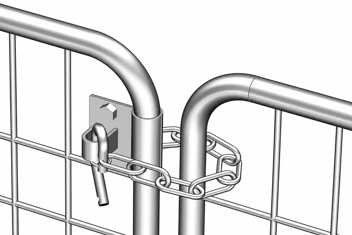
Build the hardware schedule by function
| Function | Typical component | Separate point to resolve |
|---|---|---|
| Retain the gate closed | Latch and receiving part | Alignment and engagement |
| Control who can release it | Lock or access-control device | Required operating and escape arrangement |
| Retain an inactive leaf | Drop bolt and ground receiver | Engagement, drainage and ground condition |
| Limit travel | Designed stop | Position and load transfer |
| Hold a leaf open | Hold-open device | Reliable retention and deliberate release |
| Support the leaf | Hinges and structural support | Weight, movement and mounting |
One component may perform more than one function when specifically designed to do so. Do not assume a latch is also a structural stop or that a drop bolt can safely arrest a leaf moving under wind.
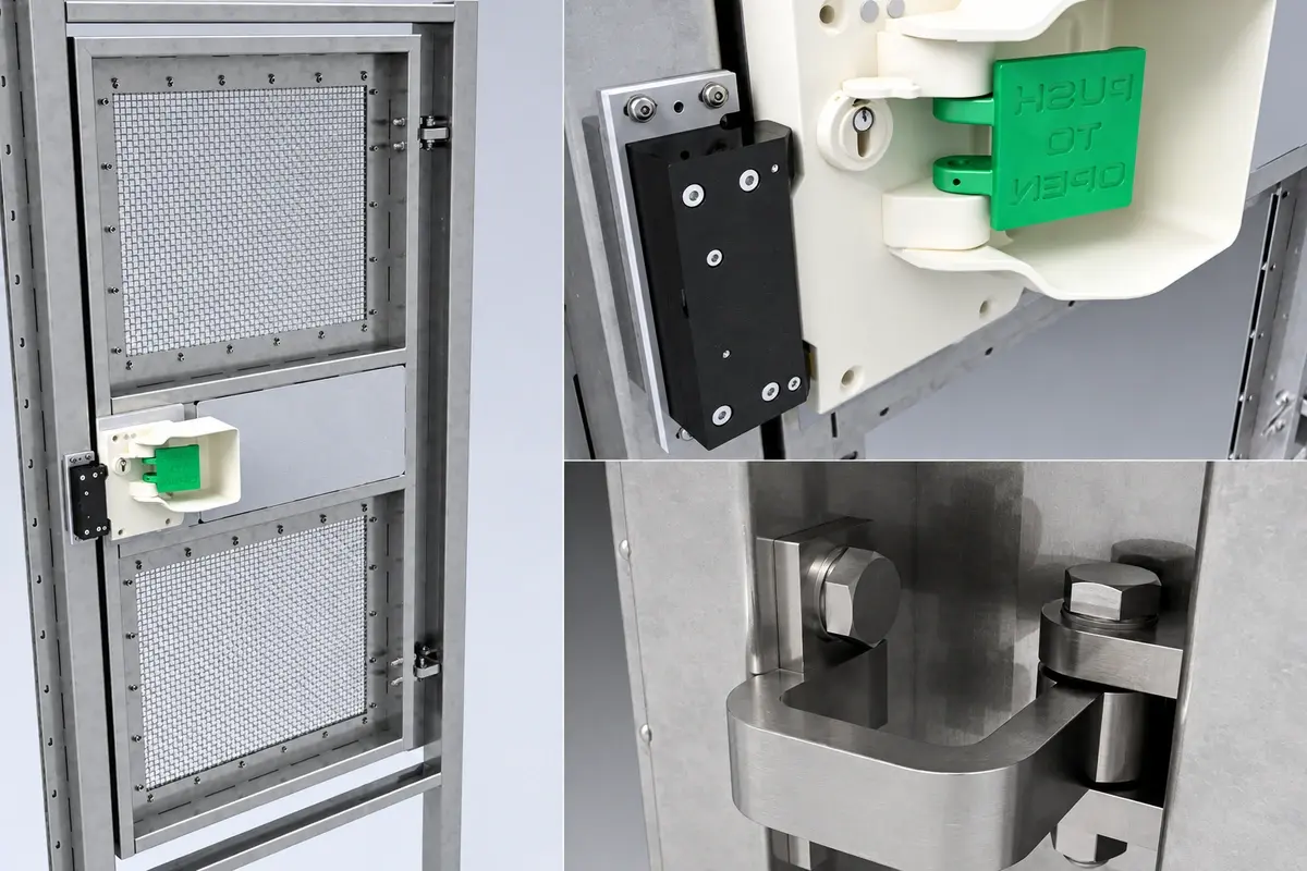
The lock schedule should describe the required function in normal operation and in relevant abnormal conditions. Where escape or powered access is involved, resolve those requirements with the responsible designer rather than adding a padlock after installation.
Calculate drop-bolt engagement from finished levels
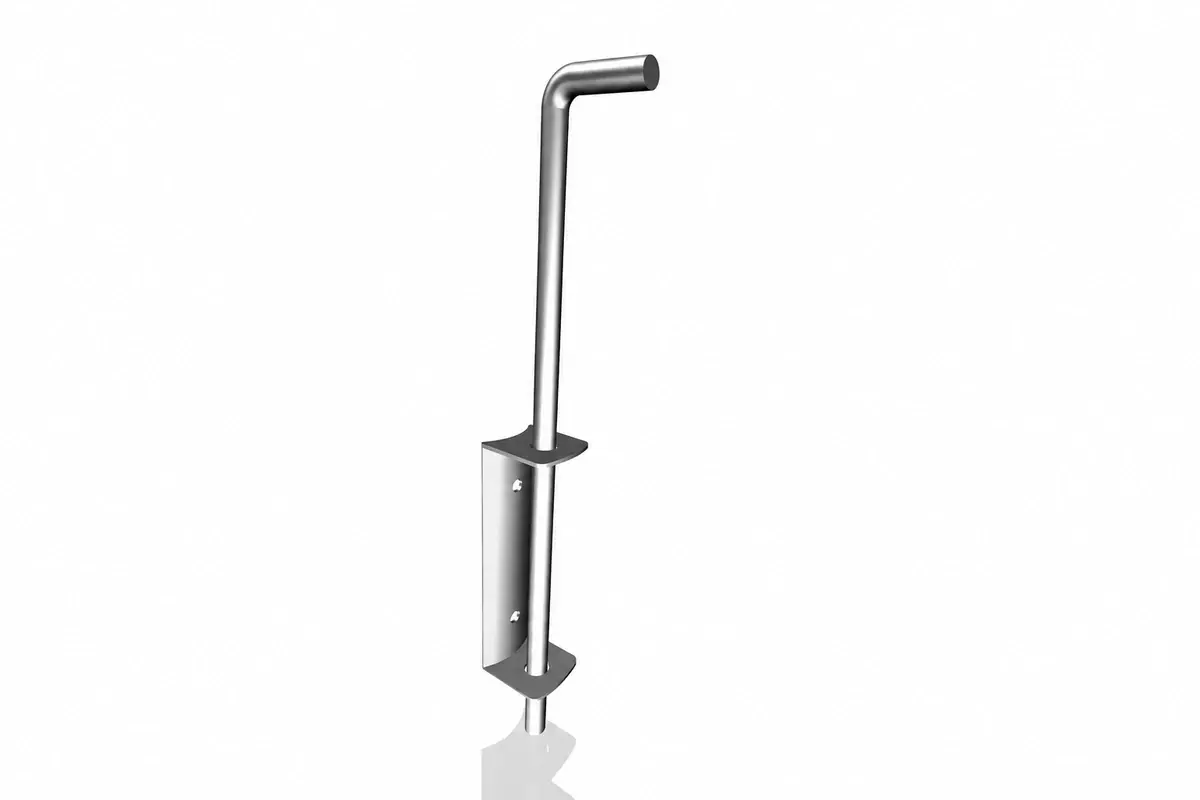
Consider an illustrative vertical bolt with 150 mm of downward travel from its fully raised position. Its tip starts 25 mm above the finished ground, and the receiver mouth is 5 mm below that surface.
The distance travelled before entering the receiver is 25 + 5 = 30 mm. The theoretical engagement after full travel is therefore:
150 − 30 = 120 mm.
If compacted debris blocks the bottom 40 mm of a receiver whose usable depth was 120 mm, the available insertion falls to 80 mm. Whether that is acceptable depends on the specified hardware and design; the calculation does not establish a minimum engagement.
Record receiver depth, drainage and access for cleaning. A hole drilled into paving without a coordinated receiver detail can fill with water, debris or ice and prevent the leaf from closing as intended.
Check engagement throughout permitted movement
Gate leaves can move slightly under load, temperature changes and wear. Inspect the latch in the actual installed position, with the leaf carrying its own weight.
For a hypothetical latch requiring 20 mm engagement, an observed engagement of 24 mm gives only 4 mm of geometric margin before that assumed minimum is reached. This is not a security rating or a universal latch requirement. It illustrates why a photograph showing a bolt barely entering a receiver is insufficient.
Measure the receiving opening, bolt extension and relative vertical alignment. Look for contact marks indicating that the latch is lifting the leaf or being forced into position.
Do not solve misalignment by enlarging a receiver opening without checking the effect on engagement and strength. Diagnose the leaf or post movement first.
Test the intended operating sequence
Use a controlled test after the gate has been installed and made safe:
- Release the lock using the intended user method.
- Open the active leaf without disturbing the retained leaf.
- Release the inactive leaf's retention and open the full entrance.
- Engage the designated hold-open devices where provided.
- Release those devices and close the inactive leaf first.
- Seat its retention correctly, then close and latch the active leaf.
- Verify locking and any required emergency release function.
Repeat the sequence from the relevant sides of the gate. Confirm that handles, keys and release controls can be used without reaching through a hazardous moving gap.
Specify the small parts that are easily omitted
Receivers, mounting plates, backing pieces, fasteners, cylinder sets and keys should appear explicitly in the supply schedule. “Lock included” may describe a lock body without the receiving or mounting parts required for the actual frame.
For 12 identical double-leaf gates, each with 2 drop bolts and 2 receivers, the project needs 24 bolts and 24 receivers before spares. Packing the bolts with the leaves but the receivers in an unlabelled common box creates an avoidable installation problem.
Use gate IDs on the packing list and retain the model references in the maintenance record. When hardware is replaced, check the engagement and operating sequence again. The missing-parts prevention guide explains how to connect the bill of materials to site issue records.