
By FencingWise Editorial Team · Updated 17 September 2026.
Separate three dimensions on the gate drawing
Record the distance between the finished inner faces of the posts, the outside width of each leaf and the unobstructed passage width in the specified open position. These dimensions are related but not interchangeable.
For a hypothetical double-leaf gate, assume:
- Finished distance between post faces: 4,200 mm.
- Hinge-side allowance: 60 mm at each side.
- Meeting gap between leaves: 30 mm.
- Equal leaf widths, measured outside the frames.
The available total leaf width is 4,200 − 60 − 60 − 30 = 4,050 mm, giving 2,025 mm per leaf.
That calculation establishes closed-position geometry only. The hinge design, opening angle, stops and projecting hardware still determine the usable passage when open. Draw the leaves in their required open position and dimension the narrowest obstruction.
Keep the 358 infill identity explicit
Specify the mesh pattern, wire directions, wire diameters and whether the dimensions refer to clear space or centre spacing. If the fence uses two layers or a profiled panel, state whether the gate uses the same arrangement.
Match gate infill to the specified 358 fence arrangement. Confirm frame sizes, safety provisions and compliance evidence for the gate being supplied; details from another system should not be copied into its schedule.
A detail that encloses the mesh inside the frame is different from one that fixes the mesh to a frame face. Show the edge support, fastening or welding arrangement and how the coating is applied after fabrication.
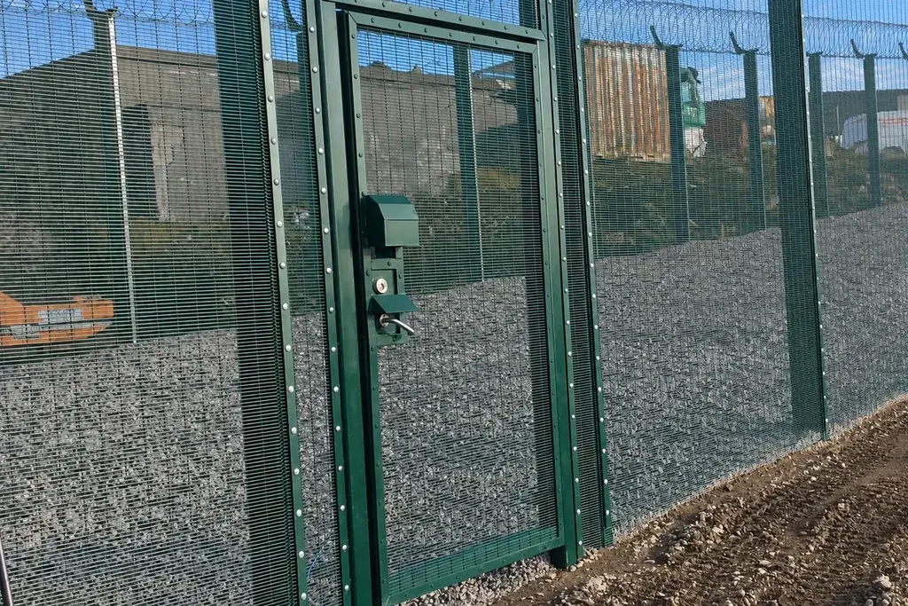
Coordinate the fixed panel beside the hinge post
The gate post has two jobs only if it has been designed for both: supporting the moving leaf and receiving the fixed fence connection. Otherwise, the adjoining panel may require its own support.
Check the local plan view. A clamp bar, projecting bolt or corner bracket must not obstruct the hinge or reduce the opening angle. Equally, opening the gate should not expose an unclosed gap behind a fence return.
| Interface | Drawing question | Site check |
|---|---|---|
| Fixed mesh to gate post | Which bracket receives the panel edge? | Correct part and full engagement |
| Hinge to leaf | What adjustment and retention are provided? | Alignment and unobstructed movement |
| Meeting stiles | What closed gap and latch engagement apply? | Gap through the operating range |
| Bottom frame | What threshold profile was used? | Clearance at the highest ground point |
| Top transition | How do fence and gate heights meet? | No unintended low section |
Treat the dimensions in this table as interfaces to resolve, not as a reason to select a generic clearance for every gate.
Survey the full swing area
A threshold survey taken only along the closed gate line can miss a rising surface inside the site. The leaf's bottom corner travels through an arc.
For an illustrative 2.025 m hinge-to-tip distance, a 90-degree opening sweeps a quarter-circle sector of approximately π × 2.025² ÷ 4 = 3.22 m². The actual obstruction envelope also includes frame thickness and hardware.
Mark spot levels within that sweep and at the leaf's outer edge. If the surface rises, investigate a different opening direction, a revised threshold or another gate arrangement before manufacture. Simply raising the leaf may create an excessive closed bottom opening.
The gate-clear-opening guide covers passage measurement in more detail.
Choose hardware as an assembly
Include hinges, leaf retention, latch or lock, drop bolts where required, stops and hold-open devices. Identify which parts are included with the gate and which are installed by another contractor.
Do not use a latch to carry a sagging leaf or a drop bolt as the sole protection against a moving leaf being blown by wind. Each component has a defined function and an installation position.
Where powered operation is intended, make that part of the gate design from the start. The motor, sensing, guarding and operating environment need coordinated assessment. A manually satisfactory leaf is not automatically a complete powered gate.
Approve the gate in a logical order
First approve the opening and movement geometry. Then approve the frame, infill and support arrangement. Finally, verify the selected hardware against those dimensions and operating requirements.
At inspection, compare the assembled gate with the drawing before it is packed. Check the closed dimensions, available adjustment, component identification and coating at fabricated joints. On site, repeat the relevant measurements using the finished posts and ground levels.
The acceptance record should state what was checked at the factory and what remains dependent on installation. This avoids treating a successful workshop assembly as proof that the final site opening and threshold will work.