
Name each connection before counting it
The pale-to-rail connection attaches the vertical pale to a horizontal rail. The rail-to-post connection transfers the assembled bay to its supports. The two connections can use different fasteners and security arrangements. A quotation stating fixings included should identify both.
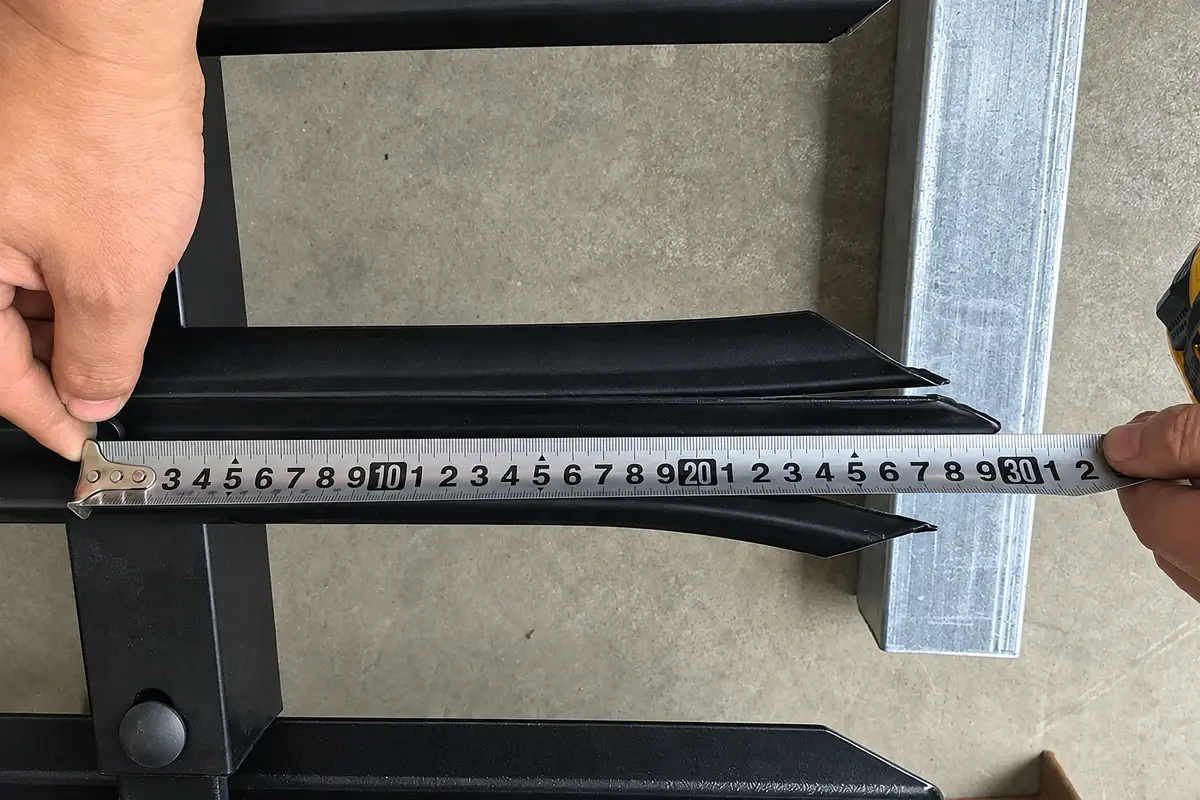
Record the pale section, thickness, length and head treatment, together with the rail section and hole pattern. A matching nominal height does not make an alternative pale compatible. Replacement holes should not be improvised on site simply because a spare part nearly fits.
Posts also have distinct duties. A line post receives adjacent bays; a terminal, corner or gate post may have different connection directions or loading. Count positions first and then assign the correct post reference to each position.
Build an illustrative ten-bay list
Assume ten bays in one open straight run, 17 pales per bay, two rails per bay, and one fastener at each pale-to-rail crossing. Suppose the approved connection uses one rail-end assembly at each end of each rail.
| Component | Calculation | Installed quantity |
|---|---|---|
| Pales | 10 × 17 | 170 |
| Rails | 10 × 2 | 20 |
| Pale fasteners | 170 × 2 | 340 |
| Rail-end assemblies | 20 × 2 | 40 |
| Post positions | 10 + 1 | 11 |
These are assumed details for a counting exercise. Each of the 40 rail-end assemblies must be broken down into its actual parts. If an assembly comprises a bracket, a bolt and a nut, that means 40 of each, not 40 miscellaneous fixings.
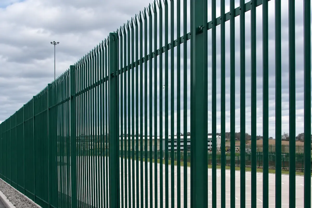
Two separate five-bay runs would still use 170 pales and 20 rails under these assumptions, but would have 12 post positions. Connecting the runs at a shared corner changes the arrangement again. A simple metres-to-posts multiplier cannot represent all three layouts.
Treat short bays as their own assemblies
A short bay may need fewer pales, a different end spacing or a special rail. Do not assume a standard rail can be cut without affecting its coating and connection. Mark the cutting and repair process on the approved detail if site cutting is permitted.
For illustration, nine standard bays at 17 pales plus one special bay at 12 pales require 165 pales. Ordering 170 does not resolve the special rail geometry. Quantity and compatibility are separate checks, and both should appear on the schedule.
At a slope, record whether rails rake and pales remain vertical, or whether the complete bay steps. The arrangement changes the connection angles and the ground-line opening. See rackable and stepped fences for the geometry distinction.
Reconcile packing by component reference
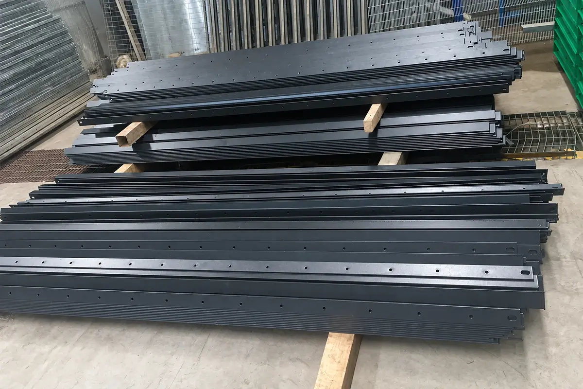
Ask for pack labels that retain the drawing and component references. Record installed quantity, separately agreed spares and total shipped quantity in separate columns. This makes a shortage visible without accidentally treating spares as material for an extra bay.
At receipt, check fastener diameter, length, thread and drive against the approved connection. A security nut that fits the thread can still be unsuitable if there is insufficient engagement or the specified tool cannot reach it. Trial-assemble the delivered parts using the intended installation tools.
Resolve a shortage without changing the system
If the delivered pale count is correct but rail-end assemblies are short, record the missing assembly reference and the exact affected quantity. Do not cannibalise special end or corner connections to complete standard bays unless the revised arrangement is approved. That can move the shortage to a less obvious location while changing the intended detail.
Check whether the apparent shortage is a counting-unit problem before ordering replacements. A carton containing clamp halves or separate nuts may have been described differently from the site's complete-assembly count. Reconcile the carton contents against the defined parts list, then identify what is genuinely absent.
For a damaged pale, retain its position and component reference when requesting a replacement. Include the adjoining rail detail if compatibility is uncertain. This enables the supplier to assess the actual interface and avoids receiving another part with the same nominal height but a different fixing pattern.
Keep one complete spare connection
For maintenance planning, retain the identity of a complete pale connection and a complete rail connection, including any component that is damaged or consumed during removal. This is more useful than a bag of unlabelled bolts left after installation.
The palisade product page describes the product scope. Use this component schedule alongside the installation drawing so procurement, packing and the site crew work from the same set of parts.