
Measure horizontal run and vertical rise
For an illustrative bay with a 2.4 m horizontal run and a 0.3 m rise, gradient is 0.3 / 2.4 = 12.5%. The slope angle is arctan(0.3 / 2.4), approximately 7.13°. The distance along the straight slope is √(2.4² + 0.3²), approximately 2.419 m.
The 2.4 m horizontal distance and 2.419 m sloping distance are different. State which one the survey supplies and which one the panel drawing requires. Confusing them can create a cumulative setting-out error over several bays.
A real boundary may change slope within a bay. Record intermediate levels at significant breaks rather than describing the entire site by one average gradient.
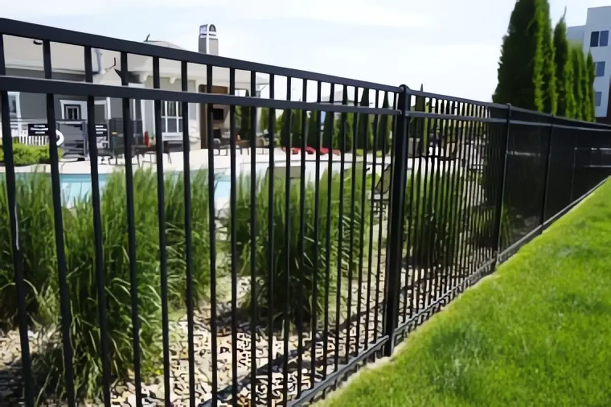
Understand what a stepped panel leaves below it
Assume a level panel sits 50 mm above the ground at the uphill end of the example bay. At the downhill end, the gap becomes 50 + 300 = 350 mm, if the ground is a straight slope and the panel underside remains level.
That 350 mm gap may conflict with containment or appearance requirements. Reducing bay length can reduce the rise within each step, but it also changes the number of posts and panels. A separate plinth or purpose-designed lower infill introduces its own design and drainage questions.
| Approach | What remains level or vertical | Main detail to resolve |
|---|---|---|
| Stepped | Panel rails remain level | Ground gap and changing post connections |
| Rackable | Typically posts and uprights remain vertical | Permitted joint rotation and changing geometry |
| Purpose-made raked panel | Geometry fabricated for the slope | Unique drawing and installation position |
Confirm the actual system behaviour. The word rackable is not permission to distort an ordinary welded panel.
Check the allowed raking arrangement
Obtain the permitted adjustment range and the associated connection details from the proposed system supplier. At greater angles, upright spacing, rail engagement and end geometry may change. A nominal panel width measured level may not equal the installed horizontal projection when raked.
For a simple illustrative member length of 2.4 m inclined at 10°, horizontal projection is 2.4 × cos(10°), approximately 2.364 m. This is a geometric example, not the actual formula for every rackable fence: the location of pivots and end fittings controls the real assembly.
Review the bottom and top of the panel at the chosen angle. A system can reach an angle mechanically while producing openings or projections unsuitable for the site.
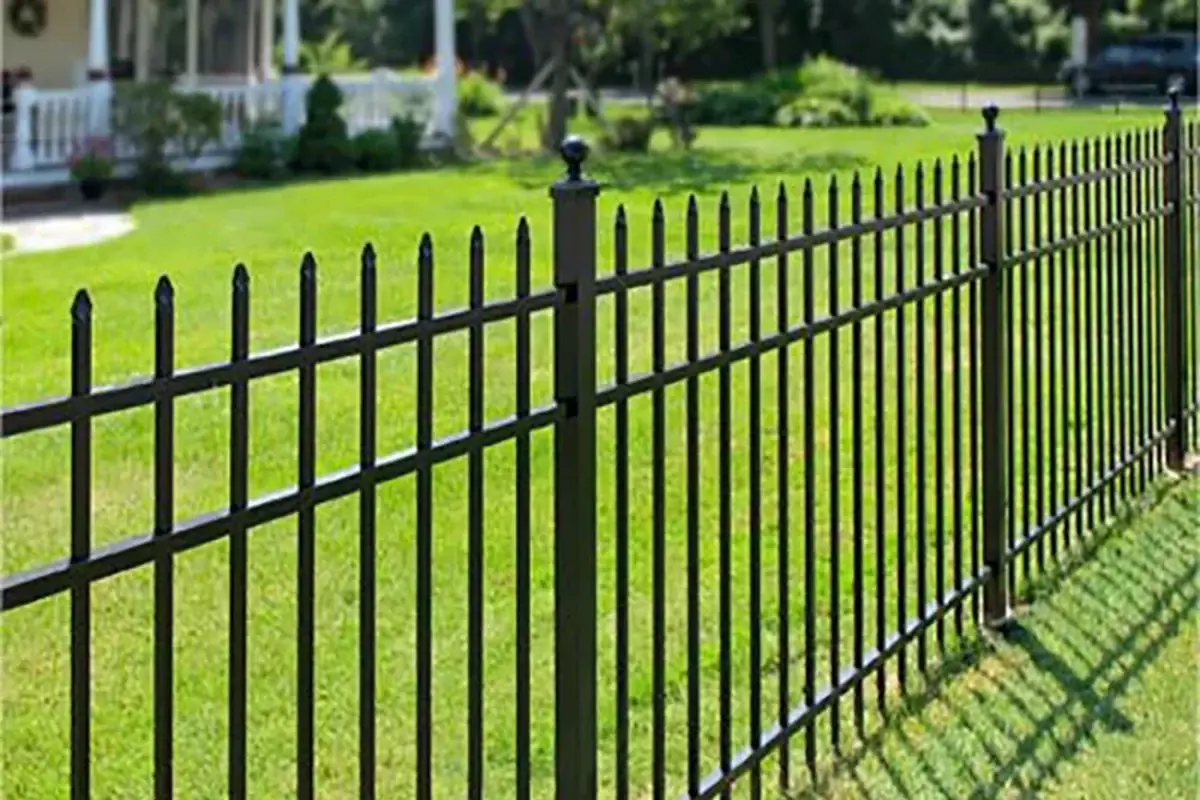
Schedule posts and special panels by position
- Mark the start datum and chainage along the boundary.
- Record ground levels at post positions and intermediate breaks.
- Choose a panel treatment for each segment and show the underside line.
- Identify longer posts, altered bracket levels and special end panels.
- Coordinate gates independently with their opening and clearance requirements.
Do not force the gate to follow a sloping panel detail. The gate's movement envelope and finished surface need a separate assessment.
Check a slope break within one panel
A single straight slope calculation is inadequate where the ground changes direction beneath the panel. Plot the intermediate high and low points and compare the proposed underside line with each of them. A panel that clears both post locations can still collide with a local mound or leave a large opening over a dip.
Decide whether to change the panel break, use a purpose-designed lower detail or revise the local ground profile through the responsible design process. Moving a post to follow a mound can affect the adjacent bay and its connection, so update the whole affected segment.
Record the finished profile after any approved ground work. The installer needs that profile and the accepted panel positions together. For replacement or later resurfacing, retain the original ground-gap assumptions so a seemingly minor level change does not create an opening or contact condition that the initial design avoided.
Check the order against the profile before fabrication
Overlay panel elevations on the surveyed profile and calculate the largest ground opening for each bay. Record which dimensions are finished survey values and which remain design assumptions. A later paving change can invalidate a carefully calculated gap.
Use drawing coordination to request the required connection views. For ornamental panels, the specification checklist explains how to preserve pattern alignment at steps and special widths. The useful output is a position-specific schedule that the installer can follow without reshaping panels on site.