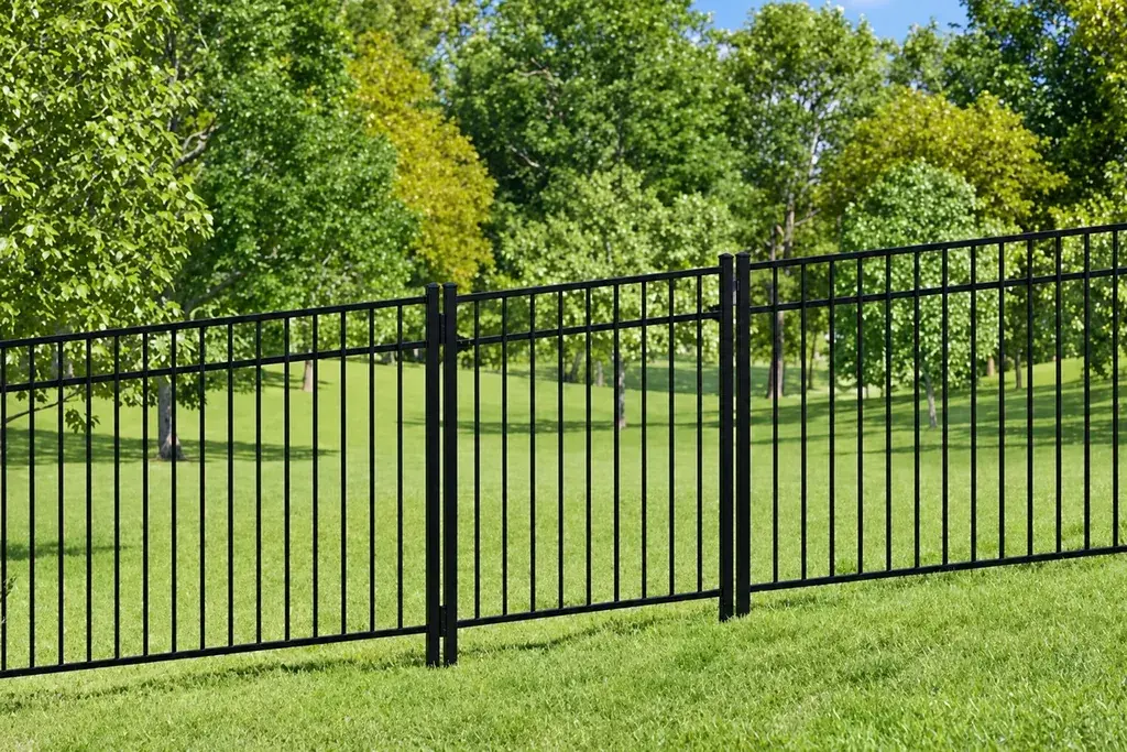
Start with the dimension you need
| Drawing dimension | What it measures | Common misreading |
|---|---|---|
| Panel width | The defined outer limits of the panel | Assuming it equals post centre spacing |
| Post pitch | Centre-to-centre distance between adjacent posts | Deducting post width a second time |
| Clear opening | Unobstructed space available for passage | Reading leaf width as usable access |
| Ground clearance | Gap from the specified finished surface to the lower edge | Measuring from unfinished excavation level |
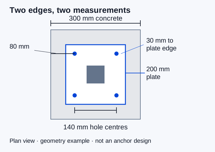
| Anchor layout | Hole centres relative to the plate and supporting structure | Measuring from a plate edge without the structural edge reference |
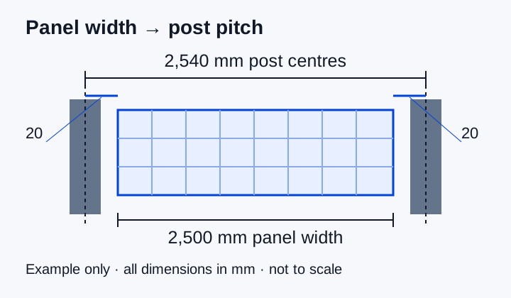
An illustrative panel connection with a 2,500 mm panel and 20 mm offset from each panel end to the adjacent post centre has a 2,540 mm pitch. This arithmetic describes that geometry only. A face-mounted system or another clamp detail can use a different relationship.
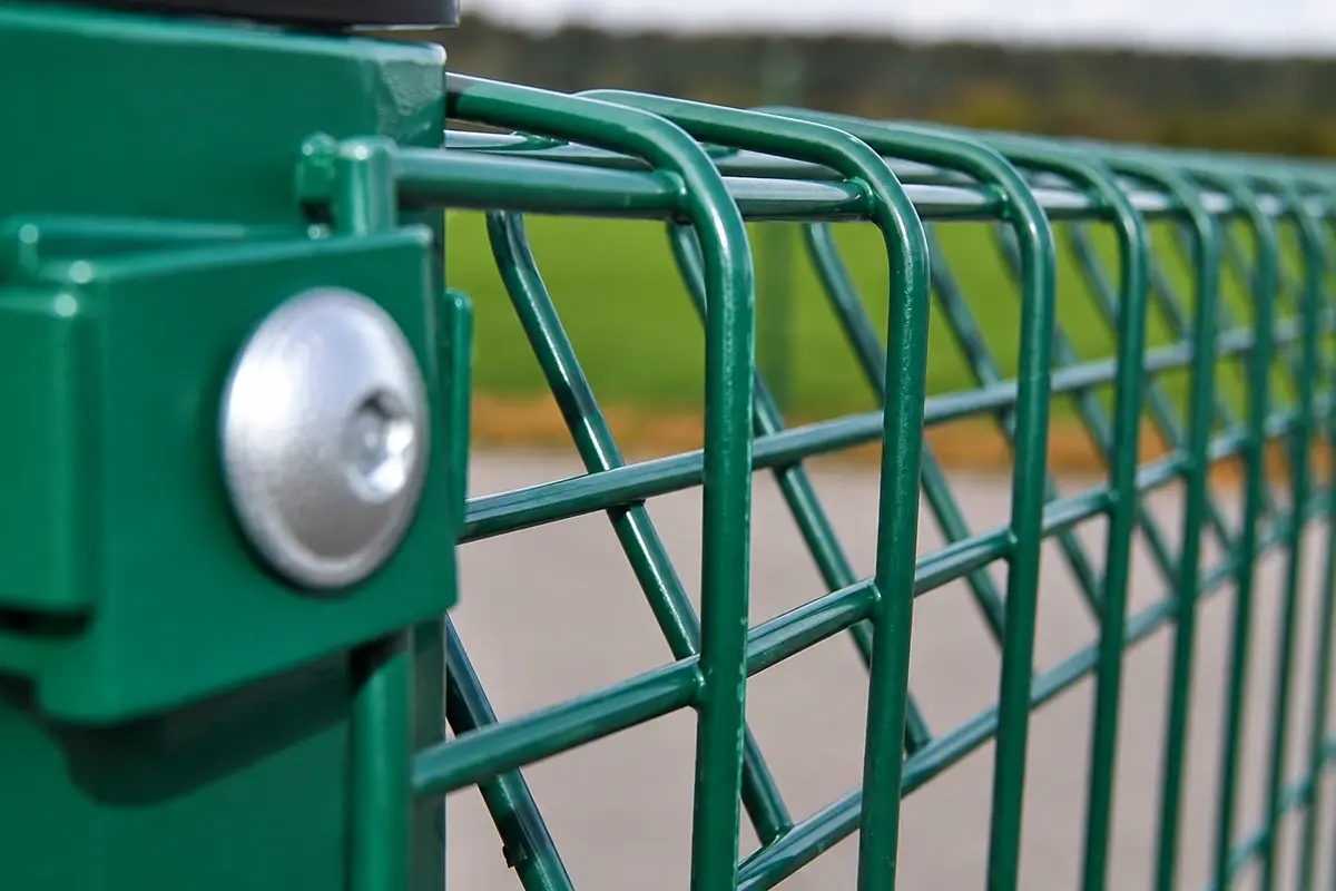
Reference diagrams available to read
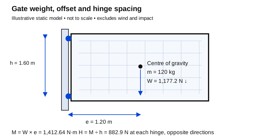
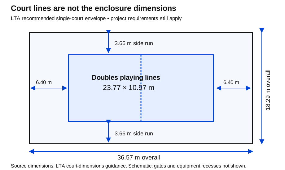
These original illustrations explain measurement methods. They are not fabrication drawings or approved designs for a supplied product.
- Gate weight and hinge spacing diagram: shows the quantities used in a simplified static load example. Read it with the hinge selection article.
-
Tennis court layout example: distinguishes playing lines and an illustrative enclosure envelope. The assumptions are explained in the tennis layout article.
-
Panel width and post-pitch diagram: shows why panel width and post spacing are different. Read the post-pitch calculation.
- Plate and concrete edge-distance diagram: separates the two reference edges in a geometry example. Use it with the anchor-interface guide.
Project-specific CAD and connection drawings are discussed against the actual enquiry. This page does not offer an unverified library of fabrication files or another manufacturer's drawings under the FencingWise name.
What to include in a drawing request
- Identify the fence system, run reference and intended use.
- Supply the current site plan, units and drawing revision.
- Mark heights, openings, changes of level and interfaces to existing construction.
- Identify the specific detail required: panel-to-post, gate support, wall junction or another connection.
- State the file format and the purpose of issue, such as quotation review or coordination.
- List the decisions still owned by the civil, structural, electrical or gate specialist.
Clear inputs reduce the risk of creating a neat drawing around an incorrect assumption. Structural foundation and anchor design are not established by a generic detail supplied for dimensional coordination.
Review before releasing material
Compare the drawing, quotation and component schedule by revision. Check units, finished dimensions, left/right orientation and the location of every special part. An approval comment should identify the sheet and detail rather than refer vaguely to the latest drawing.
If a gate width changes, review its posts, hinges, latch location and adjacent panels as well as the gate leaf. Keep an explicit record of which previous revision is superseded. A supplier should not have to guess whether an email sketch replaces the issued schedule.
Use specification support to discuss the required drawing scope, and keep the accepted documents with the installation and maintenance records.