
Draw one complete bay first
Identify whether the panel fits between posts, overlaps a face or uses a channel or clamp arrangement. Dimension the panel's finished width and the position of each adjacent post centre relative to its panel edge. Keep coating and the specified assembly clearances within the approved detail.
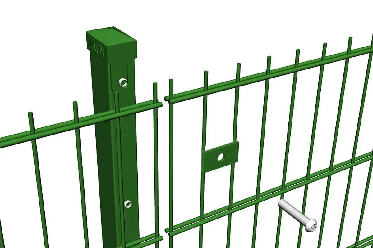
For a defined geometry, post pitch can be written as:
Pitch = panel width + left end-to-centre offset + right end-to-centre offset.
The offsets are signed distances under that definition; an overlapping arrangement may require a different sign or drawing convention. Do not assume every clamp adds the same amount. A sketch showing the actual surfaces is more reliable than a remembered allowance.
Suppose an illustrative 2,500 mm panel ends 20 mm short of the post centre at each side. The pitch is 2,500 + 20 + 20 = 2,540 mm. Setting the posts at 2,500 mm would shorten each bay by 40 mm relative to that detail.
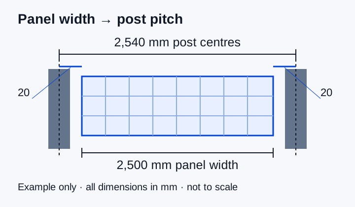
Illustrative geometry; offsets are exaggerated. Use the actual system drawing for setting out.
Count bays and post positions separately
An open straight run of 20 such bays spans 20 × 2.540 = 50.800 m between its first and last post centres. It has 21 post positions. This assumes one post at each junction and one at each end, without gates, additional supports or shared endpoints with another run.
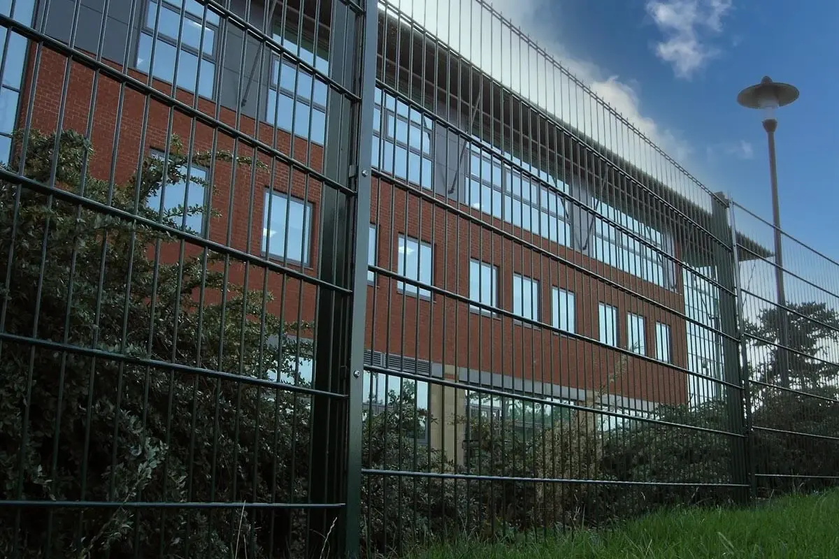
A closed loop with 20 bays normally has 20 unique post positions under the same simple arrangement because the final bay returns to the first post. The distinction matters when a quantity sheet is built from several connected lines.
| Illustrative arrangement | Bays | Unique post positions |
|---|---|---|
| One open run | 20 | 21 |
| Two independent open runs of 10 bays | 20 | 22 |
| One closed loop | 20 | 20 |
Corner and gate posts may use different components even where the number of positions is unchanged. Classify each position by duty after counting it.
Deal with the remainder explicitly
Assume a surveyed distance of 51.700 m between required endpoint post centres. Twenty full pitches occupy 50.800 m, leaving 0.900 m. That remainder is not automatically an extra full panel or a gap to distribute across every clamp.
The designer might use a special closing bay, revise the bay distribution or change the endpoint arrangement. If a closing bay uses the same two 20 mm offsets, its illustrative panel width would be 900 − 20 − 20 = 860 mm. The actual product must permit that special width, its edge treatment and its connection detail.
Do not spread 900 mm across 20 standard bays without checking the geometry. That would add 45 mm to each pitch, potentially leaving connections outside their permitted range. An adjustable slot is not permission to absorb an arbitrary surveying error.
Reset the layout at gates and changes in direction
Start each straight segment from agreed datums and account for the physical post arrangement at its endpoints. A gate opening is measured between defined faces or as clear passage, while a fence run may be scheduled between post centres. Convert these references explicitly before combining their lengths.
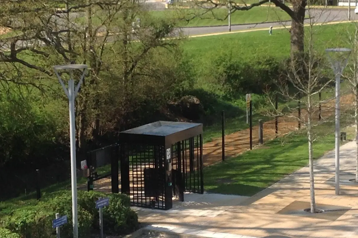
At a corner, two panels may share a post or use separate supports. At a gate, a fence panel may connect to the gate post or to an independent terminal post. The approved detail determines the count and connection; a generic “length divided by panel width” formula cannot resolve it.
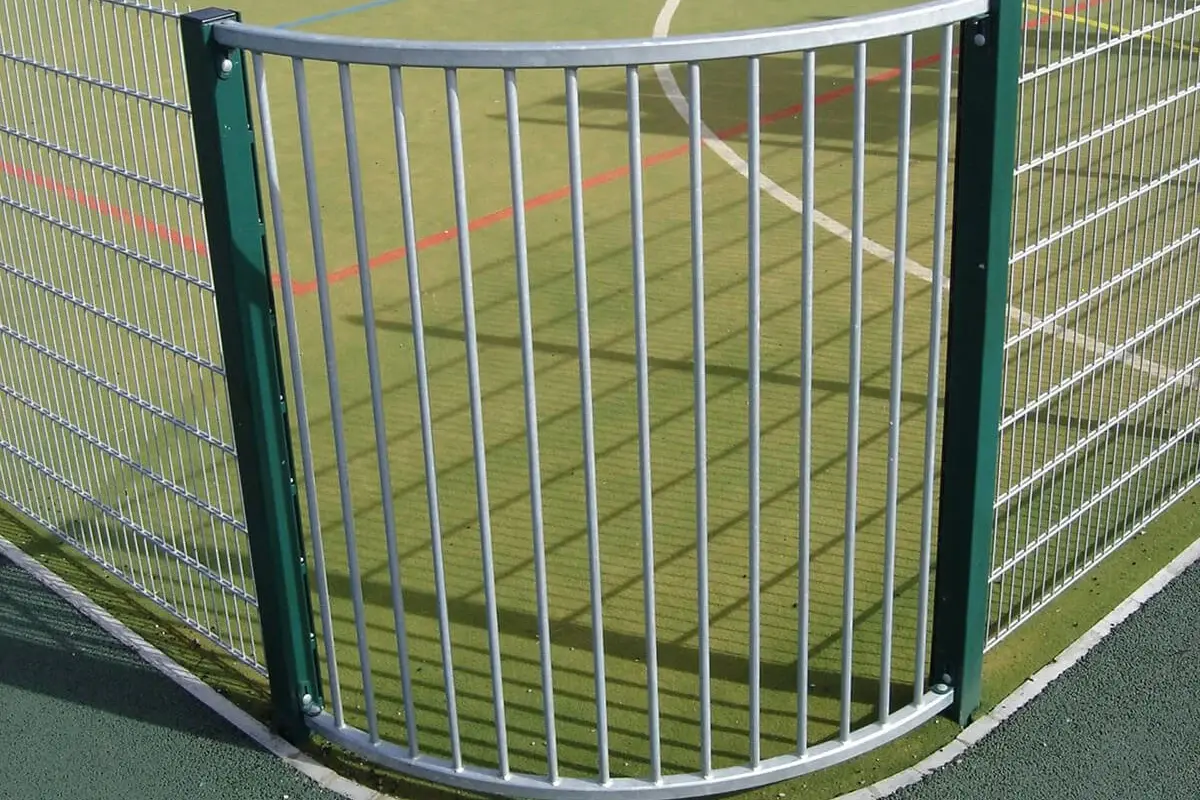
For slopes, distinguish plan distance from distance along the ground or panel line. Use stepped and raked installation planning to establish the chosen arrangement before applying the pitch calculation.
Check setting-out information before excavation
- Confirm the survey datum and endpoint coordinates.
- Select the approved bay detail and finished panel dimensions.
- Calculate pitches and identify special bays.
- Classify each support as line, terminal, corner or gate duty.
- Compare the resulting layout with services, foundations and access constraints.
- Issue the setting-out drawing with its revision and acceptance requirements.
Foundation design and underground-service controls remain separate requirements. Correct spacing does not establish that a post or foundation can resist the required loads.
Retain one accepted assembly sample or dimensional detail for checking the first installed bay. Resolve any discrepancy there before repeating it along the run. The panel-width guide explains the purchasing consequences, while installation adjustment checks addresses deviations found on site.