
Check the issued system and site information
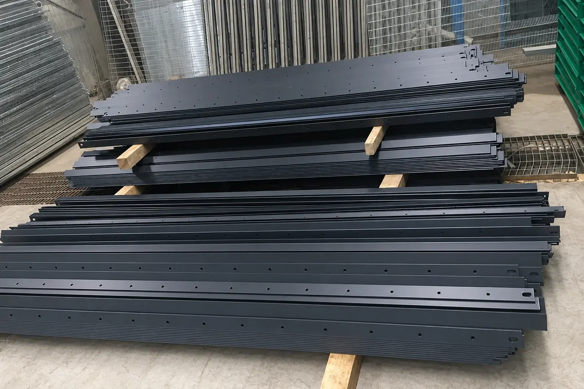
Identify the actual post, rail, pale profile, fasteners and finish. Palisade products can use different connection arrangements, so instructions for another supplier's system may not apply. Confirm the drawing revision, finished ground levels, gates, corners and special bays.
The foundation and support details require the project's design. Underground-service risks must be addressed through the contractor's safe work process; HSE guidance on underground services provides the relevant planning framework. This overview does not prescribe excavation dimensions, concrete strength or a universal post embedment.
Before unloading, establish how long components will be handled and stored without damaging their finish or exposing people to sharp profiles. Follow the site lifting and handling arrangements for the actual pack weights and component shapes.
Set out post positions from the connection detail
Use the approved centre spacing, endpoint geometry and ground profile. Do not assume rail length equals post pitch. The rail may overlap or sit within a specific post connection, and corners may need another arrangement.
Mark gates and changes of direction as separate setting-out points. Check that the completed fence line preserves the required boundary and does not create an unintended lower opening over a dip. If the design uses raked bays, the rails and pale arrangement must permit that geometry.
The post-spacing method explains how to translate panel or rail geometry into positions. It is a quantity and setting-out aid, not a substitute for the approved system detail.
Assemble a representative first bay
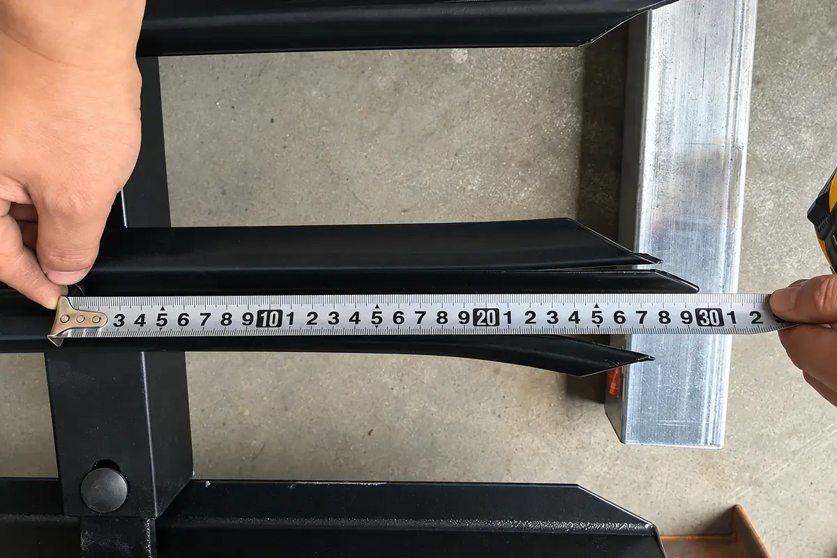
Under the manufacturer's instructions and the contractor's safe method, establish the supports, fit the rails in their specified orientation and place the pales using the defined spacing. Keep temporary support and final fixing stages distinct.
The first-bay review should cover post alignment, rail location, pale orientation, gaps, fastener access and finished height. Verify the intended top profile and any projections in relation to the site's use. Do not reverse a pale or rail merely because it appears easier to fasten.
Release the repeated work only after that assembly has been checked against the drawing. If a mismatch appears, resolve the drawing, supplied component or setting out rather than forcing the remaining parts to fit.
Count pales and fixings with explicit assumptions
For an illustrative order of 24 bays, assume each approved bay contains 17 pales and two rails. The quantities are 24 × 17 = 408 pales and 24 × 2 = 48 rails.
If the defined detail uses one pale-to-rail fixing at each of the two crossings, it needs 408 × 2 = 816 pale fixings. Rail-to-post connections are additional. If each rail has one specified connection set at each end, the 48 rails need 96 rail connection sets.
These counts describe an invented assembly for take-off practice. Actual pale numbers, rail arrangements and fastener quantities must come from the chosen system. Do not use the example as a permitted gap or installation specification.
| Example component | Installed quantity | Count basis |
|---|---|---|
| Pales | 408 | 24 bays × 17 |
| Rails | 48 | 24 bays × 2 |
| Pale fixing positions | 816 | 408 pales × 2 |
| Rail end connection sets | 96 | 48 rails × 2 |
List any spare components separately so the installed count remains auditable.
Resolve slopes, corners and cut parts deliberately
A change in level can alter top alignment and ground clearance. Use the approved stepped or raked arrangement and identify special components before cutting. A site cut may change edge condition, hole positions and corrosion protection.
Do not drill new holes, reduce a section or substitute a fastener without the appropriate approval. The change may affect both fit and performance. Record accepted alterations on the installed drawings and apply the specified protection to affected areas.
Complete the final inspection by bay reference
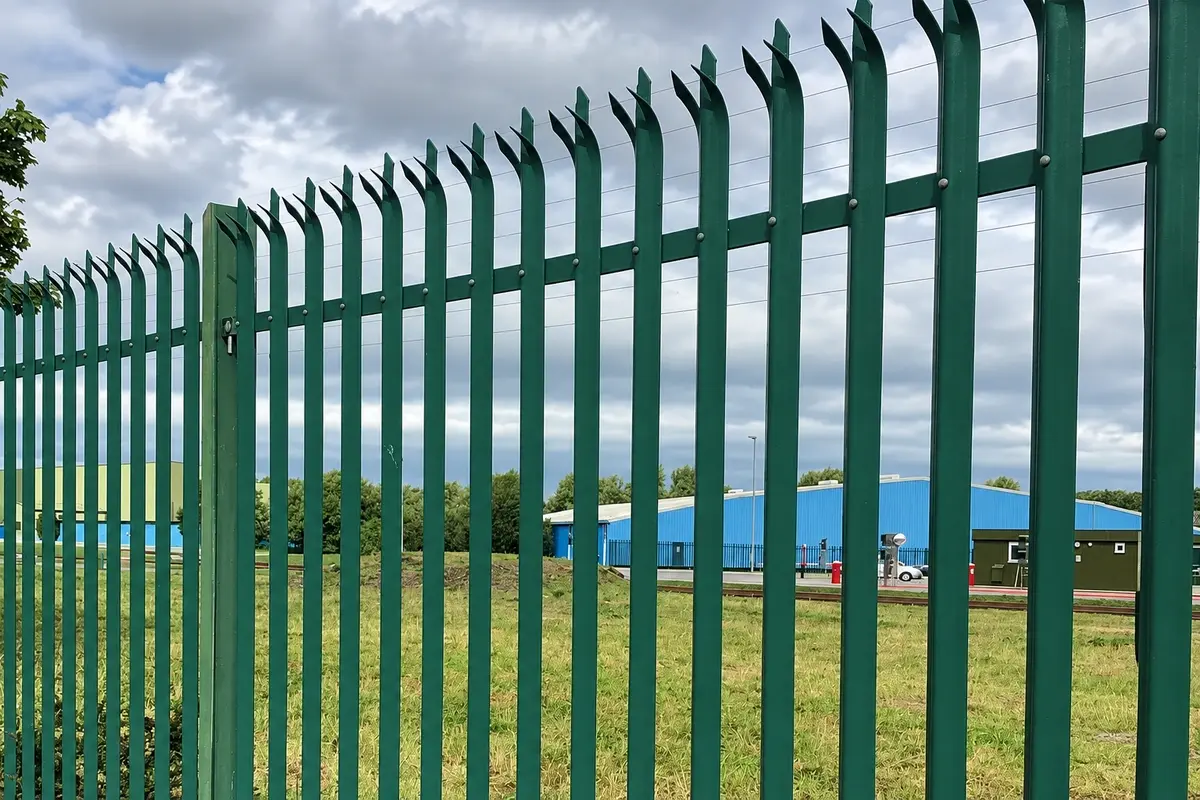
Check component identity, fastener completion, alignment, lower-edge condition, finish damage and gate interfaces against the agreed acceptance criteria. Record actual defects and their correction. A walk along the outside is not a substitute for inspecting inaccessible or concealed connections through the required procedure.
Hand over the installed layout, component references, approved alterations and maintenance instructions. The fence handover guide explains how to organise the record so later repairs preserve the same system rather than introduce visually similar but incompatible parts.