
Start with the passage requirement
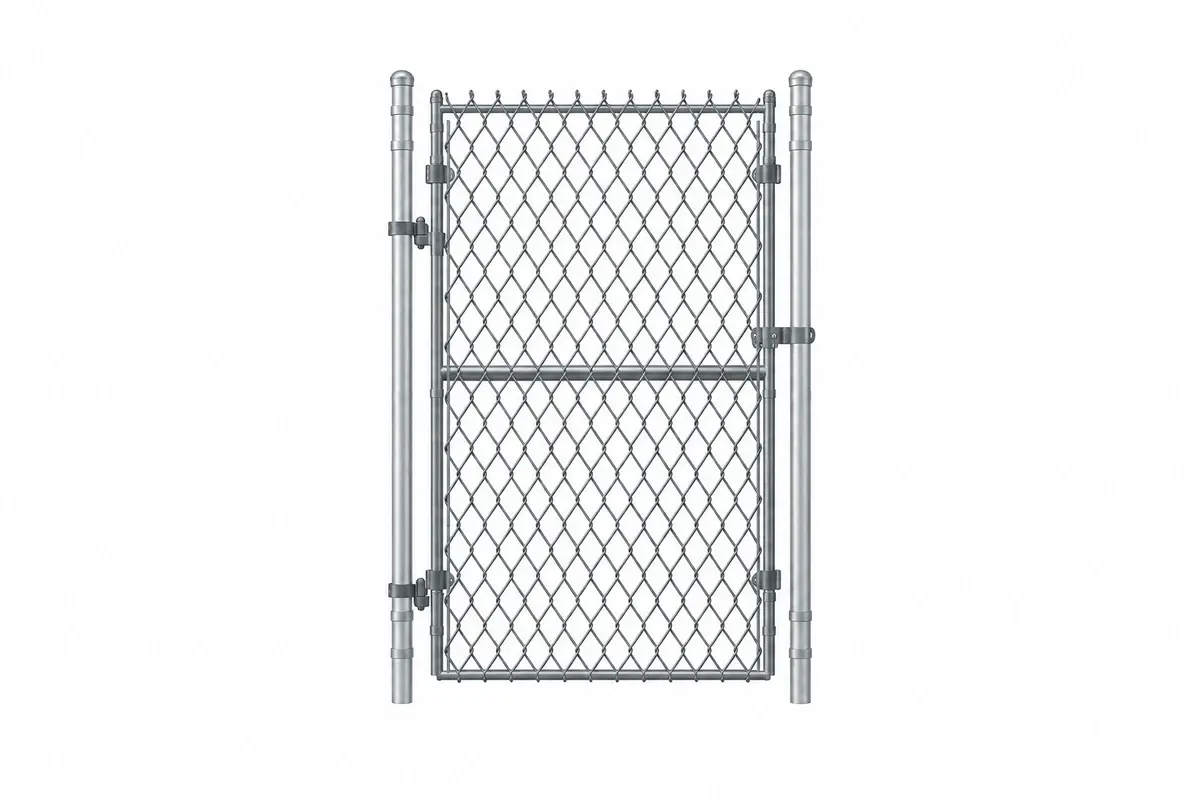
State the vehicle or pedestrian movement that must pass through the opening. Clear opening is the usable passage after posts, supports, hinges and stops are accounted for. It is not automatically the width of a gate leaf or the gap between two panel edges.
Show approach and departure paths. A vehicle that fits through a straight opening may not be able to turn into it from a narrow road. Coordinate the swept path and waiting area with the site traffic plan rather than adding an arbitrary width allowance.
Pedestrian access should be resolved separately where the operating arrangement requires separation from vehicles. Include the emergency plan and the method of controlling access outside working hours.
Draw the movement envelope
For an illustrative single leaf with a 2.0 m hinge-to-outer-edge radius opening through 90°, the idealised quarter-circle swept area is π × 2.0² / 4 = approximately 3.14 m². This geometric area excludes thickness, projections and the operator's working space.
Use the actual leaf outline on the plan, including handles, wheels and stops. Check the entire path against kerbs, stored materials, other gates and public routes. A leaf can clear an obstacle at its final open position while striking it halfway through the movement.
On sloping ground, review the vertical clearance along that path. Do not assume a wheel or hinge can accommodate an unmeasured change in level.
Assign the supports their gate duty
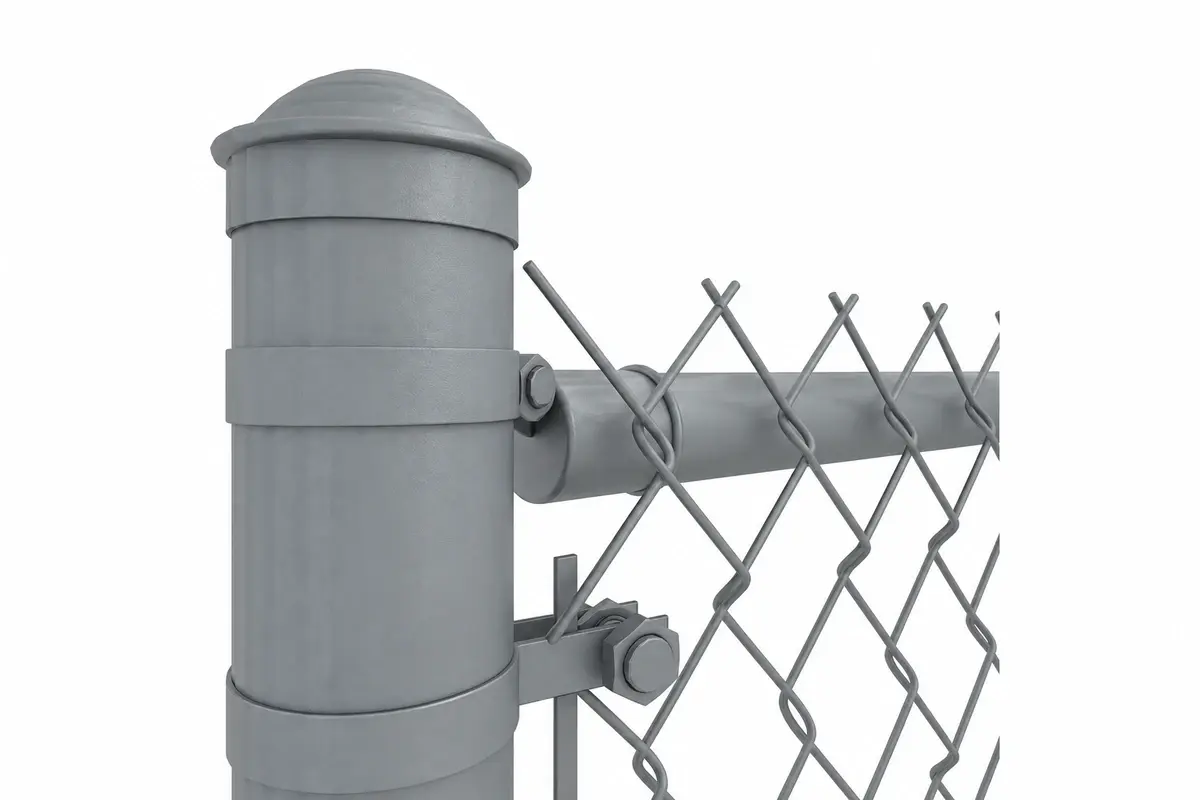
| Gate detail | Information needed |
|---|---|
| Hinged support | Approved frame, post or support assembly |
| Latch support | Closed position, latch engagement and retention |
| Open position | Approved hold-open arrangement |
| Ground contact | Surface, slope and wheel or support suitability |
| Adjacent fence | Connection that remains valid during operation |
An open gate can change the load and stability conditions of the adjoining fence. Obtain the appropriate system detail rather than treating gate supports as ordinary line feet.
HSE's site-boundary guidance discusses securing gates in their operational positions. Use that principle within the project-specific arrangement. HSE: protecting the public.
Reconcile the gate with the fence take-off
Suppose a 60 m illustrative boundary includes a 4 m vehicle opening and a 1 m pedestrian opening. The remaining fixed section is 55 m. At an assumed 2.5 m installed module, that represents 22 modules before individual run ends and connection offsets are resolved.
The 4 m clear vehicle opening does not tell you the combined leaf width or support spacing. Those dimensions come from the gate drawing. List the gate as its own assembly with its supports, hinges, latches and other approved hardware.
Keep the installed hardware quantity separate from spares. A spare coupler is not a substitute for a missing gate stop or hold-open component.
Plan for a gate that cannot be secured
The operating instructions should identify what happens if the gate will not remain in its intended open or closed position. The site may need to stop using the route and apply its established control procedure while the support or hardware is assessed. Do not ask an operator to hold a wind-affected leaf manually as an improvised substitute for the specified arrangement.
Inspect the cause before replacing a single component. Changed ground levels, a moved support or a damaged adjoining panel can affect the gate even when the latch itself is intact. Record the complete condition and compare it with the accepted drawing.
After correction, check the full movement and secured positions again. Updating the gate hardware record helps the maintenance team order a compatible replacement later. If the repair changes the arrangement, obtain the relevant approval and update the layout rather than allowing the temporary solution to become the undocumented permanent condition.
Demonstrate operation before handover
Check the identified gate through its intended range in the completed layout. Verify that the passage, support arrangement and open-position control match the approved design. Record any interference and correct it before the route is used.
The handover should identify who operates the gate, who inspects it and what happens if it cannot be secured or moved as intended. Changes to surfacing, screening or adjacent storage should trigger review of the affected detail.
Use construction-site layout planning for the surrounding routes and temporary fence inspections for the operating record. The gate schedule and site plan need to describe the same usable opening.