
Mark the controlled boundary
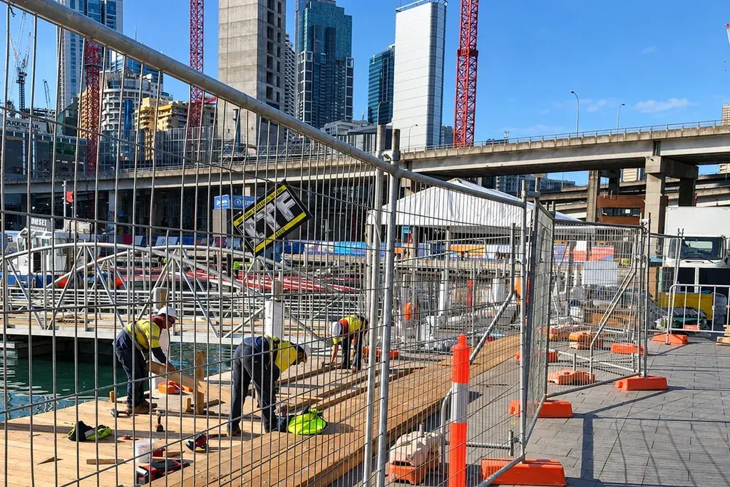
Show the legal or agreed site boundary, public routes, existing structures and the area the contractor is responsible for controlling. A fence may need to sit inside the boundary so its feet or braces do not project into public space.
HSE advises that site boundaries be defined physically where necessary using suitable fencing. The layout should reflect the actual public risk and site operation. HSE: protecting the public.
Mark locations where the ground slopes, softens, contains services or changes surface type. These conditions influence the support arrangement and the ability to use a standard detail.
Draw vehicle and pedestrian access separately
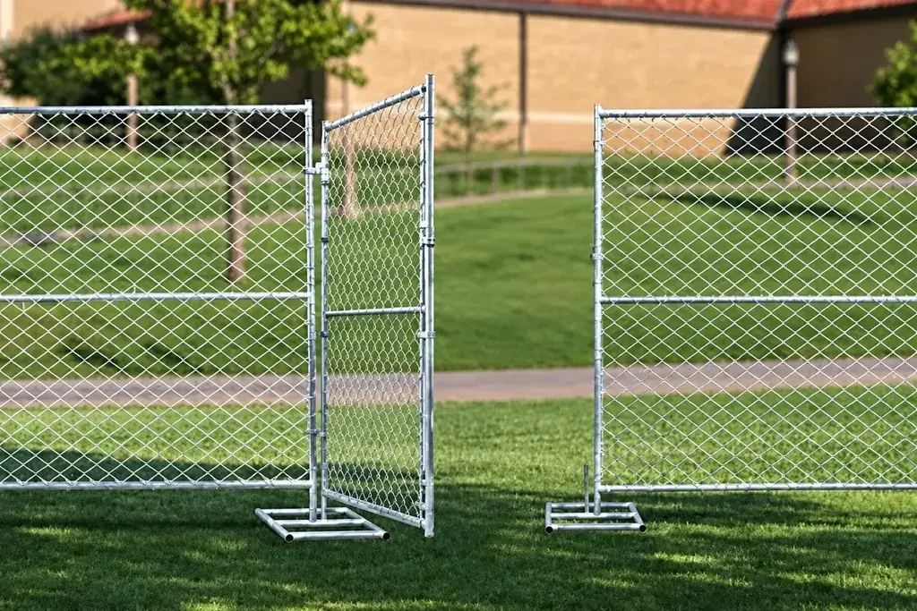
Show vehicle approach, turning, waiting and unloading areas. Identify where a vehicle can wait without blocking the footpath or forcing a gate into a public route. The fence opening alone does not prove that the vehicle can turn through it.
Pedestrian access needs its own route through the active site arrangement. Do not assume people can use a vehicle opening safely simply because the opening is wide. Coordinate the boundary with the site's traffic and emergency arrangements.
Give every opening a reference, clear passage requirement and operating state. Show where a gate leaf and its supports sit when open as well as when closed.
Prepare an illustrative length reconciliation
Assume a rectangular working enclosure 30 m by 20 m, measured along the intended fence line. Its geometric perimeter is 2 × (30 + 20) = 100 m. Suppose the drawing allocates 4 m to one vehicle opening and 1 m to a separate pedestrian opening. The remaining fixed-fence length is 95 m.
At an assumed installed module of 2.5 m, the remaining length represents 38 modules in total. That total does not show whether every individual side fits: gates, corner offsets and connection details must be assigned to their actual positions. A residual 0.5 m on one side cannot necessarily be cancelled by an extra 0.5 m elsewhere.
| Layout item | Record |
|---|---|
| Run reference | Start, end and installed length |
| Standard modules | Quantity and actual installed pitch |
| Special closure | Designed residual-bay arrangement |
| Supports | Positions and full footprint |
| Gates | Clear opening, support and swing details |
Plan the sequence of moves
For a phased project, issue a layout for each phase and describe how the boundary remains controlled during the change. Identify which panels can be reused and which additional parts are needed before dismantling begins.
An illustrative move may reuse 30 of 38 panels and add six to create a different enclosure. The final arrangement has 36 panels, while eight from the original installation remain outside that arrangement. Label their intended storage or reuse destination rather than treating them as an unexplained surplus.
Each revised layout still needs the applicable support and condition checks. Reuse of a panel does not transfer approval from its previous location.
Check the fence during a delivery
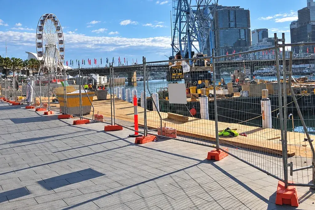
Use the planned vehicle route to examine the boundary while a delivery is being received. Show where the gate operator stands, where pedestrians are directed and where materials are temporarily placed. The closed-boundary drawing alone cannot reveal an obstruction created by a waiting vehicle or unloaded pack.
If the delivery requires removing a fence section, define the authorised opening and restoration method in advance. Identify the components that are removed and how the revised boundary is controlled during the activity. Do not leave an informal gap for the remainder of the shift because replacement couplers were misplaced.
After the delivery, inspect the restored section and the adjacent supports. Record any contact or movement before reopening the adjoining route under the site's procedure. This connects the drawing to a common real operation and helps prevent a correct initial installation from drifting into an undocumented arrangement through repeated deliveries.
Issue a layout the installation team can use
Include a revision, date, component schedule and the applicable design references. Label special connections clearly and identify any area that must remain clear for support access. Record the person responsible for accepting the installed boundary.
Use temporary fence gate planning for the access detail, and feet, clamps and braces for the parts schedule. At handover, compare the installed line with this drawing before opening the adjoining route or starting work inside the enclosure.