
Measure the foot-to-frame connection
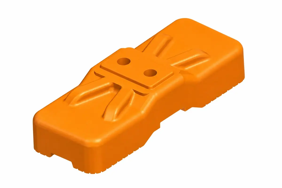
Record the frame tube shape and finished outside dimensions, socket dimensions, insertion depth and the intended orientation of the foot. Check whether adjacent panels share one foot or use separate supports. The answer changes both the quantity and the way the fence occupies the ground.
Inspect the foot for its actual duty: connection condition, damage, bearing arrangement and any identification required by the supplier. A similar-looking substitute may differ in material, mass or connection geometry.
The installed arrangement must follow its approved design and instructions. HSE identifies site fencing as temporary works; a parts count is not a stability assessment. HSE: temporary works.
Define one complete coupler
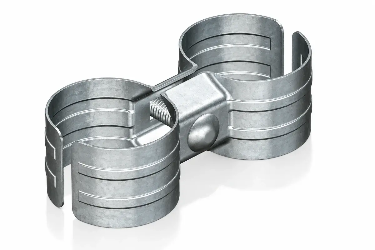
Specify the two mating frame dimensions, plate or clamp profile, bolt and nut, finish and required installation method. If a quotation counts clamp halves while the site counts complete couplers, the delivered quantity can appear twice as large as it really is.
For an illustrative open run of 25 panels, there are 24 shared junctions. At two complete couplers per junction, the run needs 48 complete couplers. If each coupler contains two clamp halves, one bolt and one nut, that means 96 halves, 48 bolts and 48 nuts.
This example excludes terminal, gate and special brace connections. It is not a universal requirement for two couplers per joint.
Keep support quantities tied to the layout
| Part | Count from | Additional check |
|---|---|---|
| Feet | Actual support positions | Shared or separate sockets |
| Couplers | Defined junction detail | Complete assemblies versus halves |
| Braces | Approved brace locations | Connection and footprint |
| Ballast | Designed support arrangement | Type, position and retention |
| Gate supports | Gate drawing | Open and closed conditions |
Under an assumed shared-foot arrangement, 25 panels in one open line have 26 foot positions. If a different system uses two dedicated feet per panel, the same panel count would imply 50 feet. Neither count is interchangeable with the other system's drawing.
Do not derive brace spacing or ballast mass from these arithmetic examples. Those depend on the assessed arrangement, exposure and ground conditions.
Check the occupied width
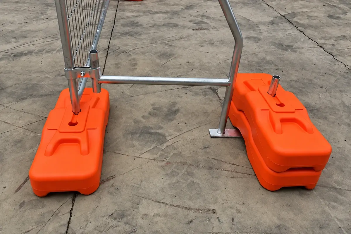
Show braces and feet in plan, including their furthest projection. A nominal fence line may fit within a narrow site boundary while its supports obstruct a pedestrian route. Record the minimum available space and the distance to adjacent operations.
For illustration, a support projects 0.8 m behind the fence and a stored pallet begins 0.6 m behind it. The overlap is 0.2 m. Moving the support without approval is not the solution; revise the layout so both the support design and the working space remain valid.
Quarantine a nearly compatible replacement foot
If a replacement foot accepts the frame only partly, stop the fit check and compare the actual dimensions and component references. Do not enlarge the socket or force the tube into place as a routine installation adjustment. The engagement and support behaviour may depend on the original geometry.
Inspect the delivered batch for a mixed component reference, damage or an incorrect finished size. Record which panels and feet were trialled so the supplier can reproduce the issue. A photograph showing only the assembled fence may not reveal where the fit is wrong.
Where the replacement is an intentional alternative, obtain the appropriate confirmation for the complete arrangement before use. Update the parts schedule and stock identification if it is accepted. Leaving the alternative unrecorded makes later repairs harder because the next crew cannot tell whether the site contains the original system or a revised combination of parts.
Trial-assemble the actual delivered components
Before distributing a large order across a site, assemble representative finished panels, feet and couplers using the specified method. Check seating, fit and access for the installation tool. Record any mismatch by component reference and batch.
Segregate unidentified substitutions until they are assessed. A bolt that can be forced through a hole or a tube that partly enters a socket is not an acceptable fit check.
Keep the component schedule with the site layout and handover inspection. This lets the installation team verify the assembly that was actually purchased, and makes replacement parts easier to identify during later moves.