
By FencingWise Editorial Team · Updated 17 September 2026.
Why forming the mesh changes its behaviour
A bend moves part of the mesh out of its original plane. That altered geometry can improve resistance to out-of-plane deformation, but the effect depends on the wire arrangement, bend geometry, panel dimensions and support conditions. “Three bends” is not a load rating.
For formed mesh panels, confirm the wire diameter, opening, height and bend arrangement on the selected product drawing. The term 3D alone does not define these specifications.
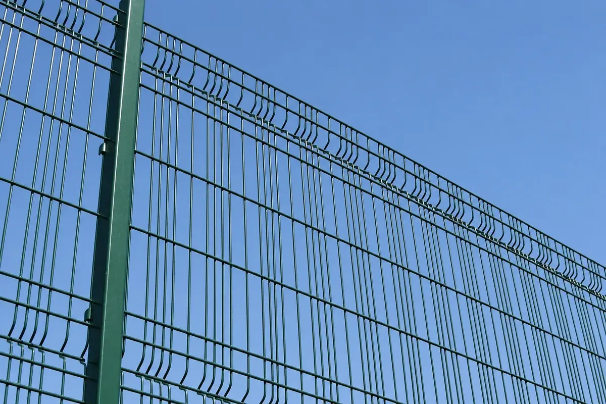
For purchasing, the practical consequence is straightforward: compare the full panel section. A deeper bend may need different clips, change the clearance to a wall or alter the packing arrangement, even when the front elevation looks similar.
Record five profile measurements
| Measurement | Reference to show on the drawing | What it helps resolve |
|---|---|---|
| Bend depth | Original face plane to the furthest formed point | Projection and nearby clearance |
| Profile band height | Upper to lower limits of the formed area | Space occupied on the panel |
| Bend centre position | Defined panel edge to the profile centre | Alignment with supports and neighbouring panels |
| Bend direction | Which side of the installed fence receives the projection | Orientation and adjacent equipment |
| Formed corner detail | Radius or approved section shape | Manufacturing and fit consistency |
Measure an actual panel supported in the agreed inspection position. If it is twisted or leaning, a depth measurement relative to the floor can include that distortion. Use a straight reference across the unprofiled face and measure from it.
For repeat orders, retain the section drawing. A photograph with a ruler across the front face cannot recover the depth of a bend.
Calculate the extra wire in a simplified V
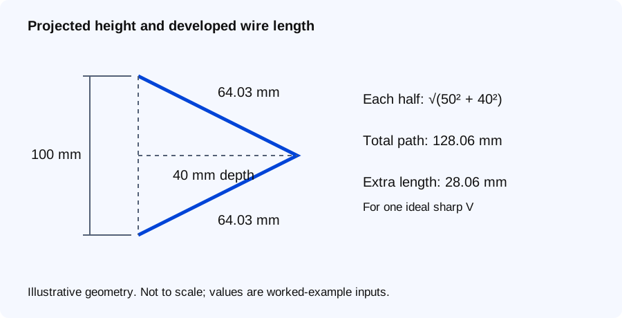
Open the full-size dimension diagram.
A formed wire has a developed length along its path, which is longer than its projected height. The distinction matters when checking a theoretical panel weight.
Assume a deliberately simplified, sharp V profile occupying a projected vertical band of 100 mm and projecting 40 mm from the original face. Each half spans 50 mm vertically. Its straight inclined length is:
√(50² + 40²) = 64.03 mm.
The two sides therefore use 128.06 mm of wire within a band projecting only 100 mm vertically. The additional developed length is:
128.06 − 100 = 28.06 mm per bend.
For three identical bends, the extra length is 84.19 mm per vertical wire, calculated before rounding. Across 41 such wires, the additional length is approximately 3.452 m.
Using the illustrative steel coefficient from the panel weight calculation and 5 mm bare wire:
Additional mass ≈ 0.006165 × 5² × 3.452 = 0.532 kg.
This model ignores bend radii and assumes the horizontal wires have no additional developed length. An actual manufacturing calculation must use the real formed section. The example explains the direction and scale of a geometric effect; it is not a product weight or a strength prediction.
Check where the clip meets the bend
A clip should seat on the wire arrangement it was designed to restrain. If a replacement panel moves its V band upwards, a fixing that previously contacted a straight wire may meet the inclined section instead. Tightening a bolt does not correct the wrong contact geometry.
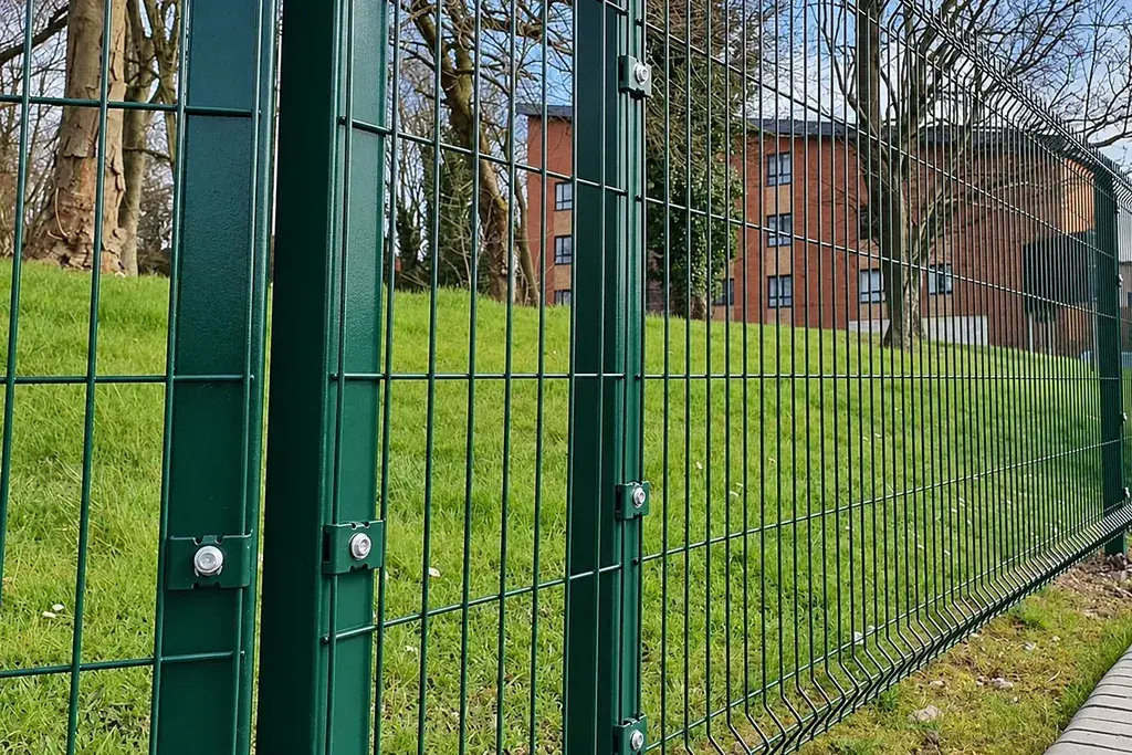
Use a trial assembly with the specified post, finished panel, clip and fastener. Inspect the seating surfaces before tightening to the component instructions. Check that the clip sits as designed and that a bolt does not bottom out before the joint is secured.
At an intermediate post, trial both adjoining panel edges. A single edge may fit while two edges, their overlaps or their projections interfere. At corners, include the actual angle rather than assuming the straight-run arrangement carries across unchanged.
Set out bend positions from one datum
A profile schedule is easier to inspect when every bend is dimensioned from the same edge. For a hypothetical 2,000 mm panel, an example could place bend centres at 300, 1,000 and 1,700 mm from the bottom datum. Those figures describe positions only; they are not recommended manufacturing dimensions.
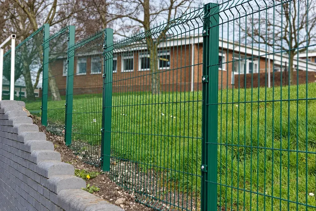
The inspector can measure each position independently. Measuring 700 mm from the first bend to the second and another 700 mm to the third makes an initial positioning error harder to see. The same principle applies when comparing a delivered panel with an approved sample.
Record the installed orientation beside the datum. Turning a panel upside down may move asymmetric bends, change exposed wire ends or place the projection on the wrong side of the fence.
Make the substitution decision from the interfaces
A proposed replacement is a reasonable candidate only after its overall dimensions, edge arrangement, profile section and connection have been compared with the original. A matching bend count is insufficient.
Where the profile differs, list the consequences: changed clips, changed post holes, extra projection, different closing-bay treatment or revised packing. Obtain the necessary design approval before accepting a change that affects the assembly.
For an unchanged system, save one measured profile record with the panel code and revision. That modest record is much more useful for future replenishment than a catalogue description that says only “3D, three bends”.