
Identify the actual supporting construction
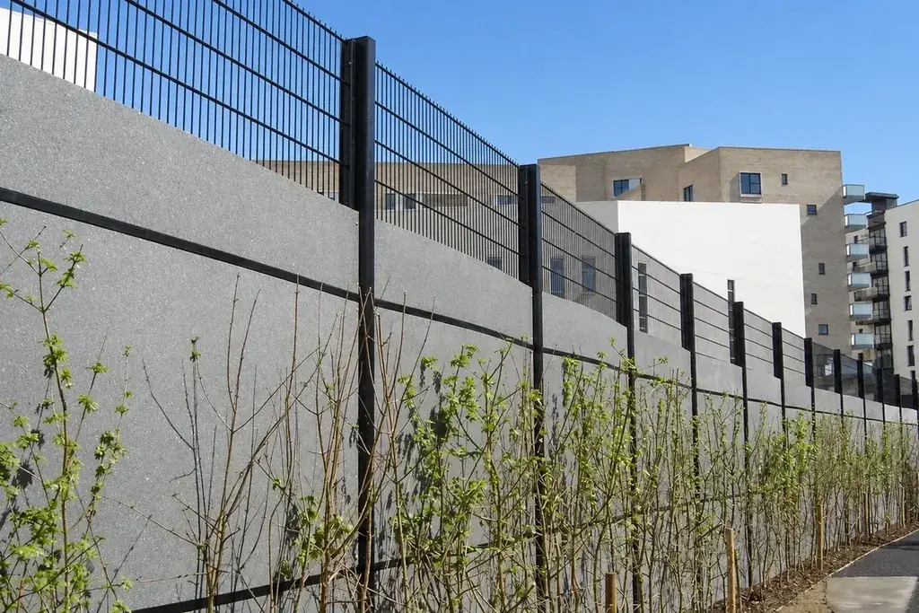
Record whether the support is reinforced concrete, solid masonry, hollow units, a retaining wall or another construction. Note its dimensions, condition, cracks, movement and any available drawings. A decorative cap or coping should not be assumed to provide structural anchorage.
The structural assessor needs to know how the wall itself is supported and what other duties it performs. A retaining wall already interacts with ground and drainage; adding a fence introduces another action and may affect both wall and foundation assessment.
Do not select an anchor from the visible surface alone. Render, cladding or a concrete-looking cap can conceal a different substrate. Investigation should be planned and carried out through the project's competent team.
Keep fence height and lever arm distinct
For a simplified geometric example, place a 1.2 m-high fence above a 0.8 m-high wall. The top of the fence is 2.0 m above adjacent ground. If a uniform horizontal load on the fence has its resultant halfway up that 1.2 m portion, the resultant acts 0.6 m above the wall top, or 1.4 m above the ground datum.
Assume an illustrative resultant of 1.0 kN. Its moment about the wall top is 0.6 kNm, while its moment about the ground datum is 1.4 kNm. These are two different reference points in the same simplified load case.
This is not a design for the wall or anchors. It omits actual wind determination, load distribution, support conditions and design factors. The example shows why a fence-only sketch cannot describe the full action on the existing structure.
Supply a section through the connection
| Information | What the designer needs to see |
|---|---|
| Wall thickness and height | Actual supporting geometry, not only visible cap width |
| Material and condition | Substrate identity and relevant investigation findings |
| Fixing location | Top or side mounting, offsets and nearby free edges |
| Fence arrangement | Height, post pitch, panel type and attached items |
| Water management | Coping, drainage, penetrations and sealing detail |
| Access | Installation, inspection and future replacement route |
Show hole centres relative to the structural edges. Plate-edge distances and masonry or concrete edge distances are different measurements, as explained in the base plate and anchor specification guide.
Select fixings for the verified substrate
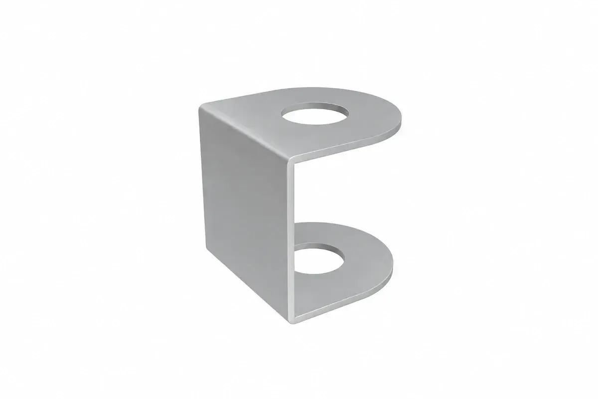
The responsible designer should specify a fixing system appropriate to the actual material, loads and installation conditions. Manufacturer instructions and approvals apply to particular products and substrates. A fixing suitable for concrete is not automatically suitable for hollow masonry, and a nominal bolt diameter does not establish capacity.
Retain the required embedment, hole preparation, spacing, edge conditions and installation method from the approved design and product information. Any site testing should follow a defined competent procedure with a clear purpose; an improvised pull or push test cannot establish the whole wall's adequacy.
If the proposed holes conflict with reinforcement, services, voids or poor material, stop that detail and obtain a revised design. Do not move the anchors a few centimetres and assume the original assessment still applies.
Preserve weather protection and maintainability
A top-mounted connection can interrupt a coping or create a route for water into the wall. A side-mounted bracket may create an offset and another water trap. Coordinate the structural fixing with the weathering detail rather than leaving sealant as an unexplained final instruction.
Make fasteners accessible for the intended inspection and replacement. If a connection is concealed after cladding or landscaping, agree how its installation will be recorded and how later condition checks will be performed.
Adding privacy screens, signs or equipment after installation changes the assembly. Refer such changes back to the responsible designer before attaching them. The original bracket count does not prove capacity for the revised exposure.
Release installation from a coordinated drawing
The final package should identify the verified wall construction, approved fence arrangement, fixing system, installation procedure and inspection requirements. Carry the drawing revision into the material order and the site record.
FencingWise can discuss fence and connection materials against those approved interfaces. Assessment of the existing wall and structural design remain project-specific work. Use the drawing guide to prepare clear inputs, and retain the installed details for future repairs rather than relying on photographs alone.