
By FencingWise Editorial Team · Updated 17 September 2026.
Give the four sides a fixed identity
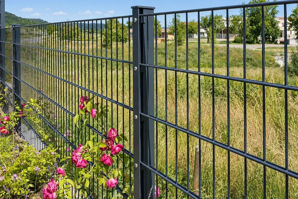
Mark the panel front, top and bottom on the drawing. Then label the left and right edges as viewed from that front. This simple convention prevents an asymmetric panel from being inspected in one orientation and installed in another.
For each side, distinguish the outermost wire surface from the centre of the last crossing wire. These are different measurement references. If a projection is dimensioned from a wire centre, the wire radius lies within the stated distance; a clear projection beyond the wire surface has another value.
The same issue appears in overall height. A height to the wire tips includes end projections. A dimension between outer horizontal-wire centres does not.
A complete height calculation
Consider a fictional flat panel with the following defined measurements:
- Distance between the centres of the outer horizontal wires: 1,900 mm.
- Top vertical-wire tips extend 30 mm above the upper centreline.
- Bottom vertical-wire tips extend 20 mm below the lower centreline.
Its tip-to-tip overall height is:
1,900 + 30 + 20 = 1,950 mm.
Now assume the outer horizontal wires are 6 mm in diameter. The top projection beyond the upper wire's outside surface is 30 − 3 = 27 mm. The equivalent bottom projection is 20 − 3 = 17 mm.
All dimensions in this example are geometric assumptions. They show why “30 mm projection” needs a reference point; they are not suggested exposed-edge lengths or an acceptance standard.
Commercial products show why orientation matters
Check the length and position of any projecting wires on the actual panel drawing. Confirm the permitted installation orientation and whether an exposed projection is suitable for the site; do not assume every panel may be reversed.
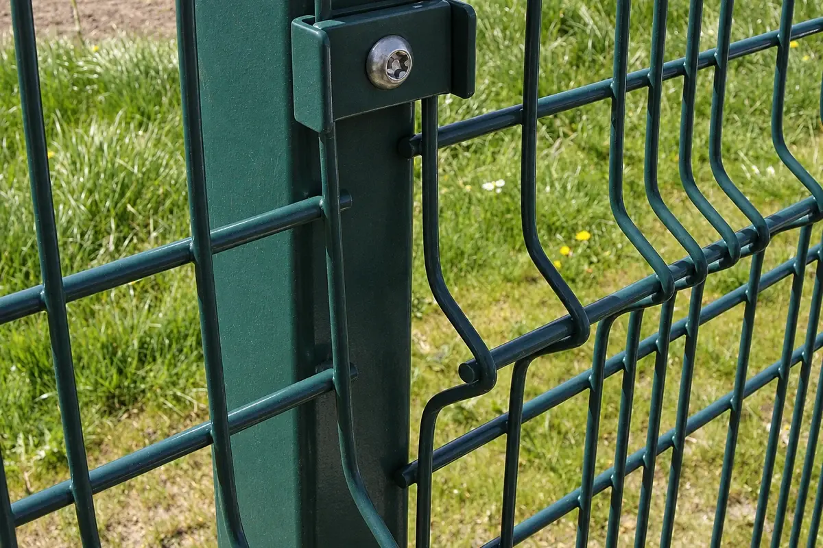
Turning a panel around or upside down can also change a bend position, fixing seat or the presentation of an asymmetric edge. Review those details together. A drawing note that merely says “install spikes down” is incomplete if the post connection or finished ground clearance was drawn for the opposite arrangement.
Where contact with users is foreseeable, the edge treatment belongs in the design review. Do not treat a change in orientation as a substitute for assessing the actual accessible detail.
Inspect the side edges at the connection
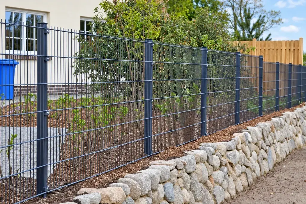
The side edge may stop before the post face, overlap a neighbouring panel or sit beneath a clamp bar. Its wire ends and outer cross-wire position determine how much mesh is captured by the fixing.
During a trial assembly, check the panel against the actual post and fixing set. Record where the bar or clip contacts the wire and whether the edge is held as shown. A long projecting end may foul a post; an edge cut too close may remove the material the clip was intended to capture.
This is particularly relevant to closing bays. Shortening a panel does not automatically create a new factory-equivalent edge. The changed geometry needs a specified fixing detail and a defined treatment for any exposed steel.
Use a six-step edge inspection
- Identify the item and revision. Match the physical panel with its edge drawing.
- Establish orientation. Photograph the top marker and the face used as the drawing reference.
- Measure overall dimensions. Use the same outer references stated on the drawing.
- Measure the four edge details. Record projections from the stated centres or surfaces; do not mix them.
- Inspect the finish. Look for observed damage, burrs or interrupted coating at the defined edges.
- Trial the relevant connection. Include the side edge and, where applicable, adjacent panels.
The number of panels inspected and the permitted deviations come from the agreed inspection plan. These steps define what to do with an identified sample; they do not set a shipment sampling rate.
Handle an edge discrepancy without creating another one
Suppose the order calls for a panel height measured to the tips, but the delivered height matches the drawing only when measured between cross-wire centres. Record both measurements and hold the affected item for review. Do not solve the discrepancy by rewriting the inspection record to use the more favourable reference.
Similarly, if wire ends obstruct a clamp, do not immediately trim them. First determine whether the wrong panel, wrong clip, incorrect orientation or a dimensional deviation caused the interference. Cutting may conceal the original cause and introduce a coating issue.
The panel dimensions and tolerances guide explains how to compare measured values with defined limits. Keep the original observation with any corrective decision.
Order replacement edges as carefully as replacement panels
A future buyer needs the overall size, wire arrangement, projections, orientation and connection reference. A catalogue height alone may identify several different edge configurations.
For repeat orders, retain a dimensioned edge photograph and the approved drawing with the panel reference. If an edge channel or other separate protection is part of the design, give it its own component code and quantity. It should appear in the material schedule and packing record, not remain an informal note remembered by one installer.
That record lets a replacement match the existing fence without relying on trial cutting or guesswork at the post.