Start at the edges of the finished sheet
Show where the outside wires finish in relation to the stated height and width. A cut through a mesh opening leaves projecting wire ends; a cut close to an edge wire creates a different perimeter. Neither is adequately described by mesh spacing alone.
For framed infill, mark the intended overlap or clearance on all four sides. Keep the frame opening, mesh dimensions and completed assembly dimensions as separate drawing values.
Centre spacing and clear opening
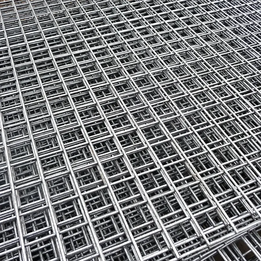
Wire-centre spacing is measured between the centres of adjacent parallel wires. The clear opening is the unobstructed space between their surfaces. For a regular grid of equal parallel wires, the clear dimension in that direction is the centre spacing minus the diameter of those wires.
Use the same measurement basis throughout the order. If the opening is important to the application, specify the required finished clear opening rather than relying on a nominal mesh name.
Receiving a mixed panel order
| Check | Record |
|---|---|
| Identity | Part number and drawing revision on the pack |
| Outline | Height, width and edge-wire arrangement |
| Grid | Wire size and spacing in each direction |
| Condition | Visible distortion, damaged intersections or coating damage |
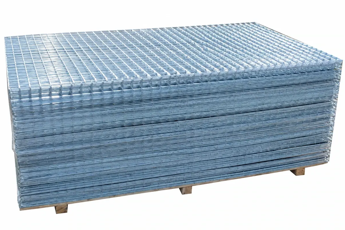
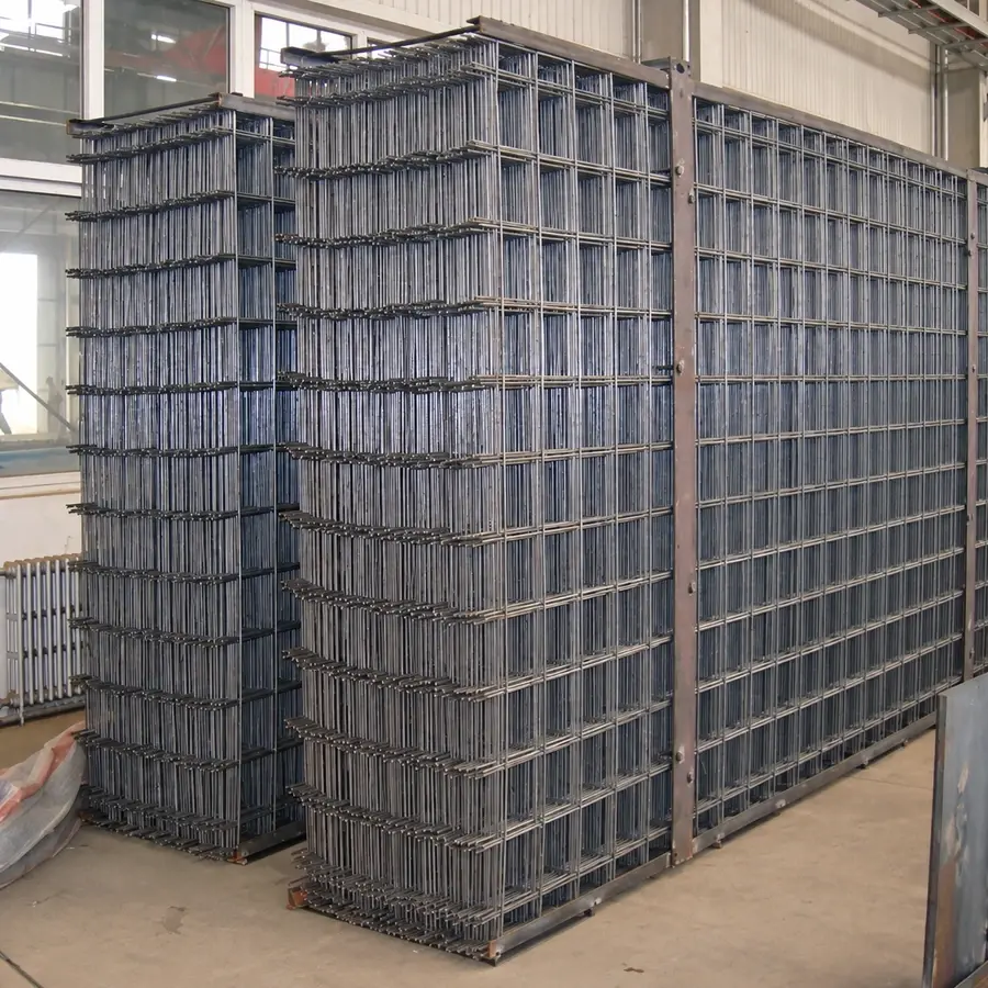
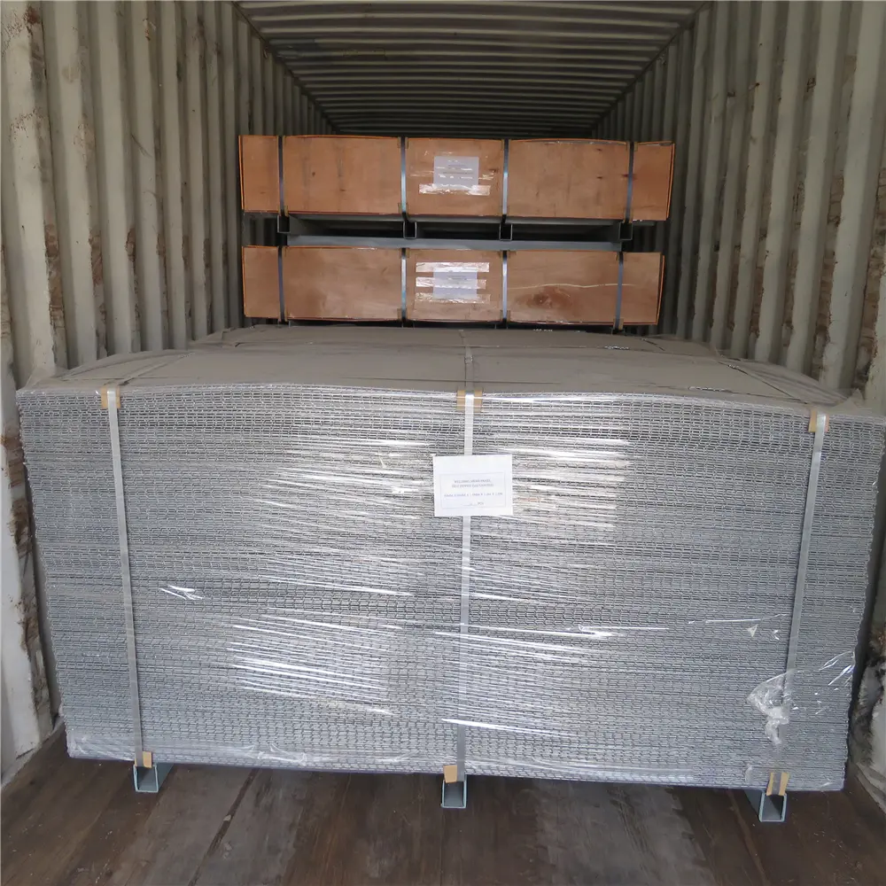
| Quantity | Sheets per pack and number of packs |
Agree tolerances and acceptance requirements before manufacture. A visual examination can record visible weld condition; it does not establish weld strength without the specified test method.
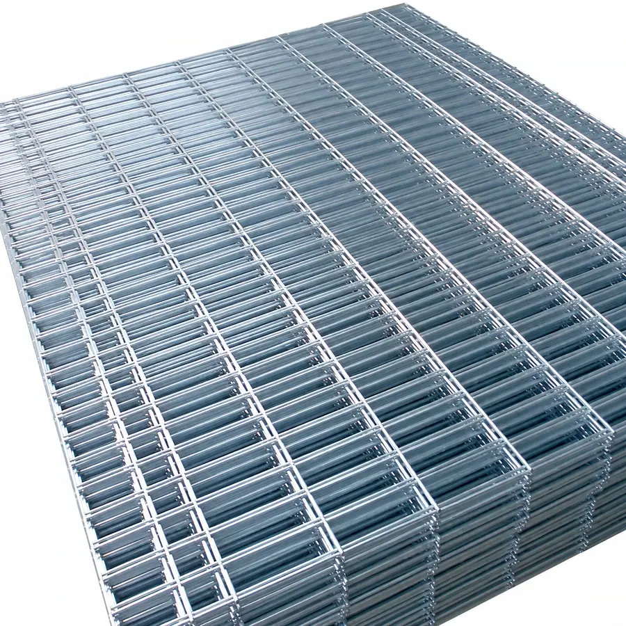
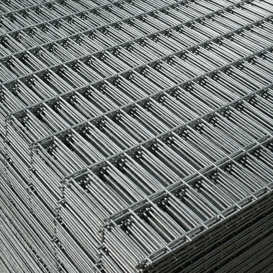
Flat single-wire panels, 656 double wire panels and 3D profiled panels have different constructions. Identify the required one in the enquiry rather than using “welded mesh” as the complete specification.