
By FencingWise Editorial Team · Updated 17 September 2026.
Start by separating three questions: what dimension is specified, what was measured, and which acceptance rule applies.
Build the measurement sheet before opening the pack
List each required characteristic with its nominal value, permitted limits and drawing reference. Width, height, squareness, profile depth and wire spacing should have separate entries.
For each entry, state the measuring position. A width between outer wire tips is different from one between wire centres. On a profiled panel, the measuring plane also matters. Record whether the sample is measured as a free component or in a defined support arrangement.
Include the instrument and its identification. A tape can be appropriate for a large overall dimension, while a smaller feature may need callipers or a depth gauge. The instrument's resolution and verified condition must be suitable for the permitted variation. A result near a limit needs the agreed decision rule, including measurement uncertainty where relevant.
Check the overall width and height systematically
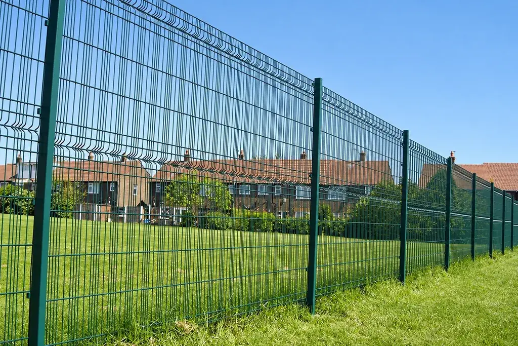
Place the panel on suitable supports so the measurement does not include avoidable sag or twist. Identify the front face and bottom datum. Remove packaging that obstructs the measurement without damaging the finish.
An illustrative inspection plan could measure width near the top, middle and bottom, and height at the left, centre and right. These six locations are a proposed recording method, not a universal standard or a shipment sampling plan.
Keep every reading. Multiple readings reveal taper, bow or inconsistent edges that one overall measurement could miss. If the specification applies a limit at every defined location, averaging the values cannot turn an out-of-limit position into a pass.
Work through a tolerance decision
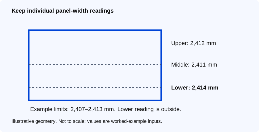
Open the full-size dimension diagram.
Assume a fictional order specifies an overall width of 2,410 ± 3 mm, measured at three defined heights. For this example, the agreed limits are inclusive and the measurement system is suitable for the decision.
The permitted interval is:
2,410 − 3 = 2,407 mm to 2,410 + 3 = 2,413 mm.
| Position | Observed width | Difference from nominal | Example decision |
|---|---|---|---|
| Upper | 2,412 mm | +2 mm | Within the specified interval |
| Middle | 2,411 mm | +1 mm | Within the specified interval |
| Lower | 2,414 mm | +4 mm | Outside the specified interval |
The average is 2,412.33 mm, which lies inside the interval. Nevertheless, the lower reading does not comply with the example's requirement at each position. The correct result is a recorded discrepancy, not a pass based on the average.
The ±3 mm value is invented for this demonstration. It is not FencingWise's standard tolerance and must not be transferred to another order without agreement.
Use diagonals to investigate shape
For an ideal rectangle, the diagonal is calculated from width and height. A hypothetical rectangle measuring 2,400 × 2,000 mm has an ideal diagonal of:
√(2,400² + 2,000²) = 3,124.10 mm.
Measuring both diagonals can help reveal a shape discrepancy. However, equal diagonals alone do not prove that the panel meets every requirement for width, height, flatness or squareness. Identify the same corner references on both measurements and use the specified method for judging squareness.
If one corner includes a projecting wire end while another uses a cross-wire centre, the comparison is invalid before any tolerance is considered. Dimensioned photographs make these reference choices visible.
Do not use a diagonal calculation across the projected face to infer the developed wire length through a V-bend. Those are different measurements.
Inspect profiles and apertures separately
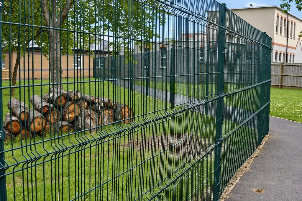
On formed panels, measure bend depth and bend position from a consistent datum. A panel may meet overall height while its middle bend is misplaced. That can interfere with a fixing designed to contact a particular part of the profile.
For mesh openings, distinguish centres from clear gaps and record the wire direction. The aperture guide explains the convention. The V-bend calculation shows why projected and developed dimensions differ.
These checks should be separate rows on the inspection sheet. A correct overall width does not demonstrate correct mesh spacing.
Record and resolve a nonconforming result
When a result is outside the defined limit, retain the item reference, location, reading and photograph. Identify the represented batch and prevent the observed sample from being mixed back into unmarked goods.
Then follow the agreed disposition route: verify the measurement, assess the affected quantity, propose correction or replacement, and obtain the required approval. A concession means a specific deviation has been accepted by the authorised party; it does not mean the drawing always allowed that value.
After correction, record the new result against the original observation. Check related characteristics where the correction could affect them. Straightening a panel, for example, can alter another dimension or its coating condition.
Separate sample results from shipment claims
An inspection record should say how many panels were examined, how they were selected and which goods they represent. Measuring one accessible panel establishes readings for that panel; it does not establish that every panel in a container complies.
The third-party inspection preparation guide explains how to arrange access, sampling and reporting. Used together, the inspection plan and dimensional sheet give the buyer a defensible result: identified measurements compared with an agreed requirement, with discrepancies still visible.