
By FencingWise Editorial Team · Updated 17 September 2026.
The quickest way to resolve the ambiguity is to separate the name into three subjects: panel shape, wire construction and installed dimensions.
Flat and profiled describe shape
A flat panel has no deliberate projecting stiffening bands across its face. A profiled panel has bends, commonly V-shaped, that give the mesh depth. These bends need a section drawing because their depth and position are difficult to judge from a front elevation.
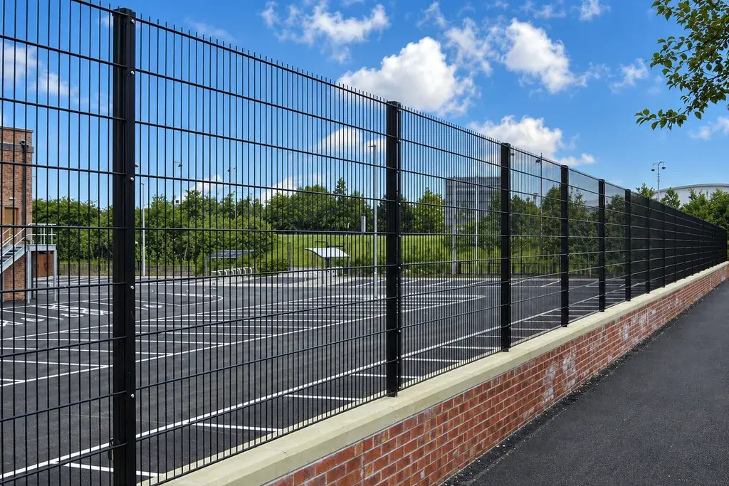
Flat twin-wire panels and formed mesh panels have different constructions. Confirm the wire arrangement, bends and dimensions on the selected product drawing; a family name alone is not a universal dimensional standard.
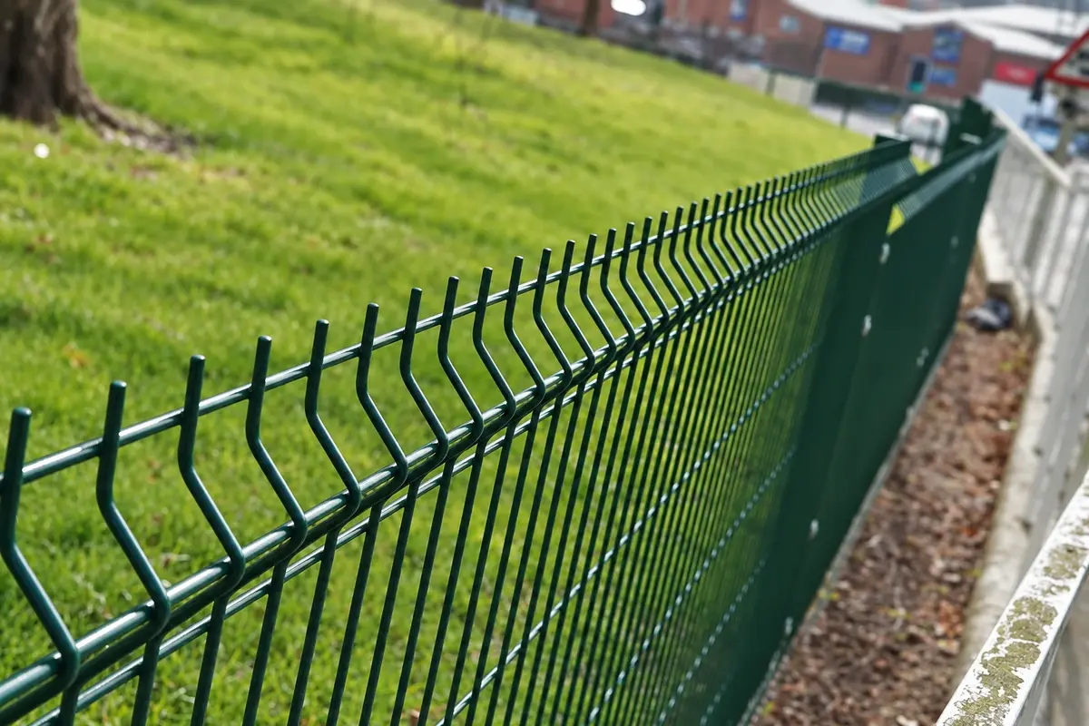
Do not assume that all flat mesh is double wire. Flat 358 mesh is another construction. Conversely, a panel can combine a close mesh pattern with profiling. The shape label and mesh pattern answer different questions.
Read 656 and 868 as a wire arrangement
For the usual twin-wire notation:
| Name | First horizontal wire | Vertical wire | Second horizontal wire |
|---|---|---|---|
| 656 | 6 mm | 5 mm | 6 mm |
| 868 | 8 mm | 6 mm | 8 mm |
These are nominal wire references, not three aperture dimensions. The two horizontal wires lie on opposite sides of the vertical wire. The order should be stated on the drawing so someone reading the schedule does not interpret “656” as a model with no dimensional meaning.
The description must also distinguish steel diameter from finished coated diameter. A measurement over powder or polymer coating is not automatically a measurement of the steel beneath it. Keep the measurement basis in the specification alongside the numbers.
Changing from 656 to 868 affects more than a label. The connection must accommodate the selected arrangement. See the 656 and 868 comparison for the consequences across the material package.
Four dimensions that need separate entries
A buyer should be able to point to each of the following on a drawing:
- Overall panel width: the defined left-to-right extent of the supplied mesh.
- Overall panel height: with the top and bottom measuring references identified.
- Profile depth: for formed mesh, measured from a stated face or reference plane.
- Installed bay dimension: normally a defined distance between supports, derived from the connection.
A fifth detail often changes the height interpretation: projecting wire ends. A stated height measured to the outermost wire tips differs from a height measured between the outer horizontal wires. Neither should be silently substituted for the other.
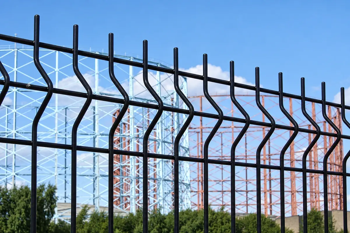
In a sample inspection, use the front elevation for width, height and aperture, then a side view for profile depth. Trying to describe all these measurements with one photograph creates avoidable ambiguity.
Translate a vague request into measurable information
Consider this fictional enquiry: “200 panels, 2D, 2 m high, green.”
It tells the supplier a quantity and a broad appearance, but leaves several choices unresolved. An illustrative completed specification could instead read:
| Field | Example entry |
|---|---|
| Quantity | 200 panels |
| Form | Flat twin-wire mesh |
| Wire reference | 6/5/6 mm nominal steel-wire arrangement |
| Mesh reference | 50 mm horizontal × 200 mm vertical, wire centres |
| Overall height | 2,000 mm, including specified end projections |
| Overall width | 2,410 mm between defined outer references |
| Edge drawing | ED-01, revision B |
| Connection | C-01, revision B |
| Finish | Separate coating schedule and approved colour sample |
These entries are hypothetical purchasing data, not FencingWise stock dimensions. They demonstrate how the name is replaced by a defined item. A separate tolerance schedule would state the acceptance limits; none are implied by the example.
The revised request is easier to price because the supplier can flag a proposed difference against a specific field instead of treating “2D” as permission to choose every other detail.
Prove that the panel fits the intended bay
For an illustrative panel mounted between 60 mm wide posts, assume 15 mm between each panel edge and the adjacent post face. With a 2,410 mm panel:
Post-centre spacing = 2,410 + 15 + 15 + 30 + 30 = 2,500 mm.
The 30 mm terms are half the width of each post. A different face-mounted or overlapping joint needs a different relationship. These are geometric assumptions, not installation clearances recommended for all systems.
This example explains why a “2.5 m panel” and a “2.5 m bay” cannot be treated as interchangeable descriptions. Resolve the connection first, then use the layout method to calculate quantities.
Check a quotation in the same order
Start with the panel form, then wire arrangement, dimensions, edges and connection. Check coating and quantity after the physical item is identifiable. Mark substitutions next to the affected field: a changed wire reference, an added bend, a different finished width or another edge detail.
Finally, identify what the quoted unit contains. A panel may be supplied alone, with a defined fixing set, or as part of a panel-and-post package. None of those inclusions follows automatically from “2D” or “3D”.
The resulting specification should allow a second person to identify and measure the same panel without seeing the original sales conversation. That is the point at which the name becomes useful purchasing information.