
Describe the deployed geometry
Concertina arrangements form a three-dimensional coil pattern when deployed according to their design. Flat-wrap arrangements present a flatter arrangement of loops along the boundary. Exact thickness, height and coverage depend on the identified product and installation detail.
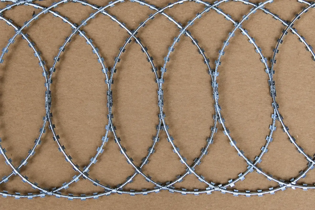
A flatter form can be relevant where available space is limited, but it does not automatically deliver a higher security rating. Nor does a larger coil automatically establish a better system. Compare the evidence and site suitability for the actual configuration.
Check the installed envelope on the supplier's dimensioned drawing. Packed coil diameter, deployed height and projection beyond the fence face are separate measurements; a quotation should identify each one that affects the available space.
Calculate the order from declared coverage
Suppose an illustrative boundary requires 96 m of topping coverage. One identified package covers 8 m under its stated installation arrangement; another covers 12 m under its own approved arrangement. The simple counts are 96 / 8 = 12 packages and 96 / 12 = 8 packages.

These counts are comparable only if both arrangements meet the project duty and account for the required ends, corners and connections. If an approved take-off requires another 4 m of coverage, the respective rounded package counts become 13 and 9. The surplus coverage is a purchasing consequence, not permission to change deployment spacing.
| Field | Record for each proposal |
|---|---|
| Packed dimensions | Transport and storage envelope |
| Installed coverage | Length under a stated deployment condition |
| Installed envelope | Height, width and projections |
| Supports | References, spacing and attachment detail from the design |
| Special junctions | Ends, corners and gate transitions |
Check the support and access envelope
Show the topping in section relative to the fence face and the property boundary. Include the support arm, connections and any projection beyond the regular fence. A system that fits in elevation may still interfere with a maintenance route or gate swing in plan.
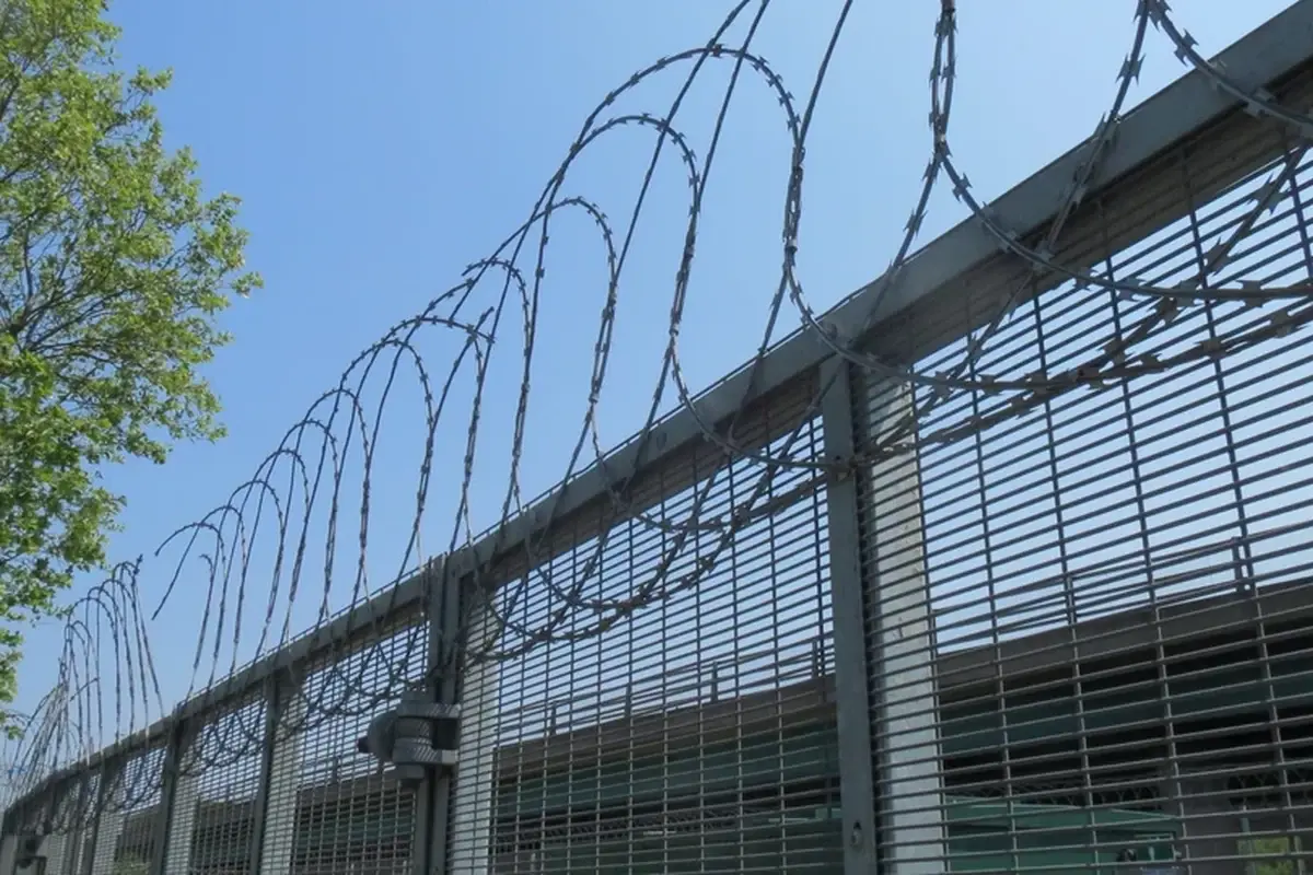
Where the topping crosses a moving gate, review both open and closed states. Do not assume the fixed-line detail can be continued across a hinge without a separate assessment.
The post and foundation design must suit the complete arrangement. Space compatibility is only one check; the supporting system still needs the relevant structural and operational review.
Compare delivered packages and installation information
Ask for pack identification, material and coating details, the applicable installation method and the components included. Record whether clips or other connection parts are supplied and how they are identified. Do not substitute loose parts based on a visual resemblance.
Handling sharp coils requires a controlled method and competent personnel. Retain the supplier's applicable handling and installation information; do not use a coverage calculation as a deployment instruction.
For an importer, keep the package reference tied to the final installed drawing. This helps distinguish a transport shortage from a change in the coverage assumption.
Check a discontinuity at a gate or corner
Mark where the regular topping arrangement stops and restarts. Gate frames, hinges and corners can change the installed envelope and support direction. A simple total length does not identify the special components or geometry required at those positions.
Obtain the relevant junction detail before confirming the package count. If the design uses a different form at a transition, list it separately rather than including it in a generic coil allowance. The quotation should make clear which parts complete each transition.
During handover, retain the location and product references for those special sections. Future replacements should reproduce the accepted arrangement instead of continuing a standard coil across a location that was deliberately treated differently. This is particularly useful where maintenance access or gate movement depends on a controlled clearance and a later substitution could obstruct it.
Decide on the whole boundary arrangement
Select the form that meets the site duty within the available envelope and has an appropriate documented support arrangement. Record why it was selected and what would trigger review, such as changed gates, adjacent access or a different package specification.
Use barbed wire versus razor wire for the broader construction comparison and topping-arm geometry for the mounting interface. Keep the final purchase reference specific enough that a replacement cannot silently change the boundary's configuration.