
Follow the manufacturing sequence
A component fabricated before galvanising has a different history from one welded from pre-coated material. Later cutting or drilling can create new exposed surfaces in either route. Powder coating over the assembly adds another layer whose preparation and compatibility must be established.
Ask which operations occur before and after each protective treatment. Mark the welds, holes and cut ends on the drawing where their treatment differs from the general surface. This makes it possible to inspect the relevant locations rather than measuring only an easy flat face.
A weld that looks smooth under paint may still have unresolved fabrication or coating issues. Conversely, a local appearance difference is not automatically a failed protective system. Apply the agreed acceptance criteria and investigate the actual condition.
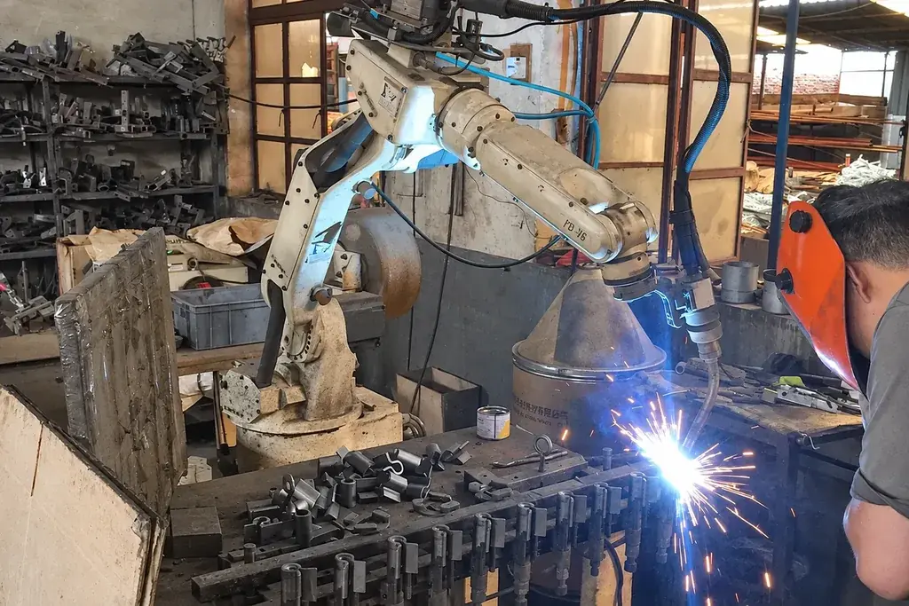
Classify the location before repairing it
| Location | First question | Record to retain |
|---|---|---|
| Welded seam | Was the protection applied before or after welding? | Fabrication and coating sequence |
| Field-cut panel edge | What substrate and coating layers are exposed? | Approved cut and repair detail |
| Drilled fixing hole | Was the hole made before finishing? | Hole location and treatment method |
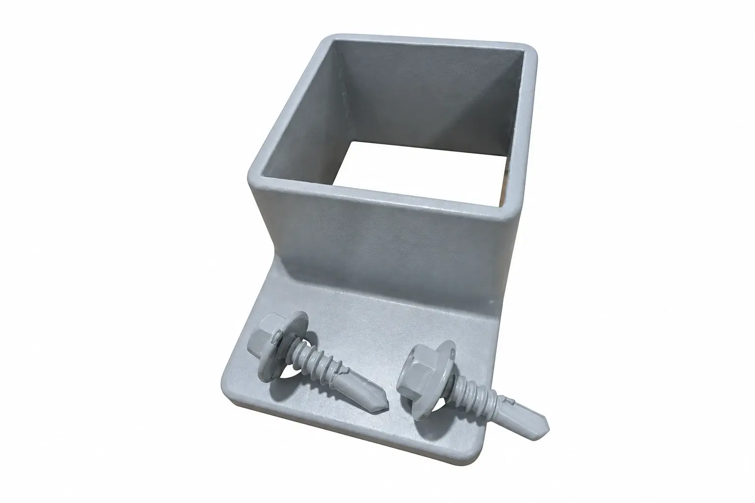
| Tightened fastener | Has assembly damaged protection or changed contact? | Fastener specification and installation result |
| Crevice under a bracket | Is water retained at the joint? | Joint geometry and repair of the underlying cause |
Do not use coating repair to conceal a cracked weld, bent component or loose connection. The structural or mechanical defect needs its own assessment before surface protection is restored.
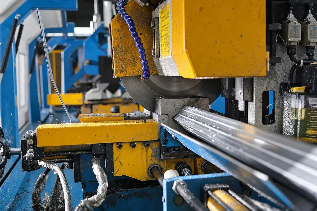
Use a repair specification that matches the original system
The Galvanizers Association's guidance on welding galvanised steel describes cleaning the welded area and suitable zinc-rich repair, typically to at least 100 micrometres unless otherwise agreed. That guidance concerns its stated galvanised-steel context; it is not a universal thickness for every coating or every site repair.
For a powder-coated assembly, identify the full repair sequence and compatible products, including any required treatment of the metallic layer. Follow product instructions for preparation, environmental conditions, application and cure. Colour matching alone does not demonstrate restored protection.
Welding and surface preparation introduce their own hazards and require competent work controls. This article is a procurement and inspection method, not a welding procedure or instruction to burn coatings off a fence in service.
Calculate the area without losing the location
Assume an illustrative inspection finds 12 damaged patches, each approximated as 25 × 40 mm. The total area is 12 × 25 × 40 = 12,000 mm², or 0.012 m².
If the inspected faces total 60 m², the visible damaged proportion is 0.012 ÷ 60 × 100 = 0.02%. That small percentage does not decide acceptance. A patch at a critical connection or a continuous exposed edge can matter differently from scattered cosmetic marks.
Record each patch's position, substrate exposure and cause. Use the repair limits in the applicable specification; do not invent an allowable percentage from this example. Nor should an approximate rectangular area be presented as a precise laboratory measurement.
Inspect the finished repair in stages
- Photograph and identify the original damage before preparation.
- Confirm that any underlying mechanical defect has been resolved.
- Check the prepared surface against the repair product's requirements.
- Record the repair material, batch where relevant and application conditions.
- Measure or inspect the completed repair using the agreed method after the required cure.
- Retain the result and any follow-up requirement with the component reference.
Measurement instruments need to suit the layer and substrate. On a layered system, a total reading may not isolate the repaired zinc or topcoat thickness. See coating thickness and mass checks for that distinction.
Prevent the same damage on the next order
If defects repeat at the same location, change the process or detail rather than treating every delivery as a touch-up exercise. Possible investigation points include contact protection in packing, cutting sequence, hole finishing, bracket drainage and access for coating application.
Use receiving photographs and repair records to identify the pattern. An approved improvement should be carried into the drawing, packing instruction or inspection plan so it survives the next reorder.
For maintenance, keep the compatible repair instructions with the asset records. Cleaning and repair planning addresses the broader sequence; this location-based review ensures that welds, cuts and fasteners receive the attention their geometry requires.