
Make the cutting file unambiguous
State units, scale, material, thickness, panel orientation and drawing revision. Identify through-cuts, marking operations, folds and fixing holes. Remove unintended duplicate or open contours through the fabricator's file-validation process.
The artwork and manufacturing drawing should correspond, but they serve different purposes. A visual image can show the intended pattern without defining border widths, ligaments or attachment zones. Those features need dimensioned geometry before the file is released.
For an illustrative imported drawing, a 1,200 mm panel misread as 1,200 inches becomes 30,480 mm. Checking a known overall dimension immediately exposes the unit error. Do not rely solely on a file extension to establish units.
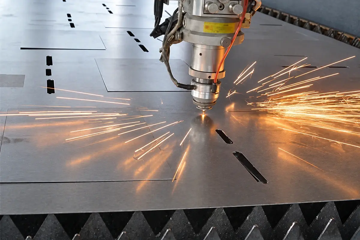
Define one coordinate system for the hole pattern
Suppose an illustrative panel is 1,000 mm wide and 1,800 mm high. Four hole centres lie 50 mm from each adjacent edge. With the bottom-left corner as origin, the coordinates are (50, 50), (950, 50), (50, 1,750) and (950, 1,750), all in millimetres.
Horizontal centre spacing is 900 mm and vertical centre spacing is 1,700 mm. Hole diameter is a separate field and cannot be inferred from those coordinates. Edge distance to the hole centre also differs from the remaining material between the hole edge and panel edge.
The values are illustrative, not an approved fastening detail. Material, loading and attachment design determine whether a real hole arrangement is suitable.
Inspect the features a pattern image can hide
| Feature | Check before release |
|---|---|
| Small retained islands | Are they connected to the panel where intended? |
| Narrow ligaments | Do they suit fabrication, finishing and service? |
| Fixing zones | Do pattern cuts conflict with the approved attachment? |
| Borders and folds | Are their dimensions and sequence defined? |
| Orientation | Is the outward face and installation position identified? |
Mirror images can have identical overall dimensions and still be wrong for a patterned elevation. Label the face and position on both the drawing and the packing list.
Follow cutting with edge and flatness checks
Inspect cut edges, burr removal, local distortion and the condition of narrow features. Record acceptance against the specified criteria rather than using a broad claim of precision cutting. If the part is folded, check the finished geometry after forming, not only the flat blank.
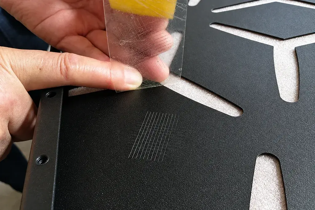
Review the surface-treatment sequence for the selected material. Edge condition and access around small cut-outs can affect the final appearance. A finish sample should represent difficult features, not only a large uninterrupted area.
For a first article, assemble the actual fixing detail to a representative support. This confirms that the finished hole pattern and the adjoining component agree, including the approved clearances.
Compare the cut file with the installation elevation
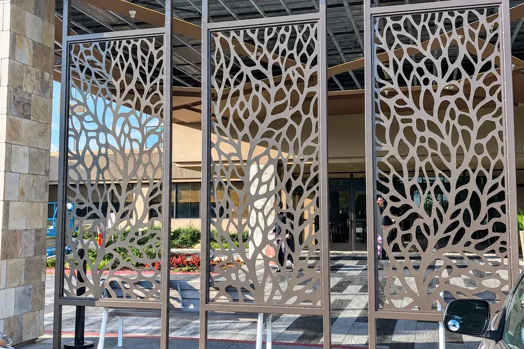
Before releasing a repeated pattern, place the manufacturing references onto the installation elevation. Check the outward face, panel sequence and pattern orientation across posts and corners. A file can be correct as an individual part while being assigned to the wrong position in the larger design.
For a revised file, identify the old and new references and the affected production status. Determine whether any parts have already been cut, finished or packed. The change decision should explicitly address those parts rather than allowing mixed revisions to enter the same shipment unnoticed.
At first-article review, compare both the measured part and its position in the elevation. Retain the approved sample or record with the released file. This links visual acceptance to the manufacturing geometry and gives replacement procurement a reliable reference when a future order needs one specific panel from a larger patterned boundary.
Preserve the approved revision through the order
Suppose a ten-panel elevation has four unique patterns and six repeats. The schedule should list ten installation positions but only the appropriate unique manufacturing references. If one end pattern changes, identify the affected position and superseded file explicitly.
Retain the accepted first-article record and file revision for replacements. A panel photographed on site cannot reliably recreate the cutting geometry or the attachment detail.
Use perforated versus laser-cut screens for pattern-area calculations and drawing coordination for the support interface. The finished inspection should verify that the right file became the right part and that the part fits its intended position.