
Use one reference for each opening
Assign a gate ID such as G01, G02 and G03, then use it on the site plan, quotation, drawing, hardware list and packing labels. Record the users and the operating duty: routine pedestrian access, delivery vehicles, maintenance plant or an emergency arrangement defined by the project.
The word pedestrian does not establish an accessibility requirement, and vehicle does not define a turning envelope. The project designer should determine the usable route and any applicable access or emergency requirements. Purchasing then preserves those dimensions in the material schedule.
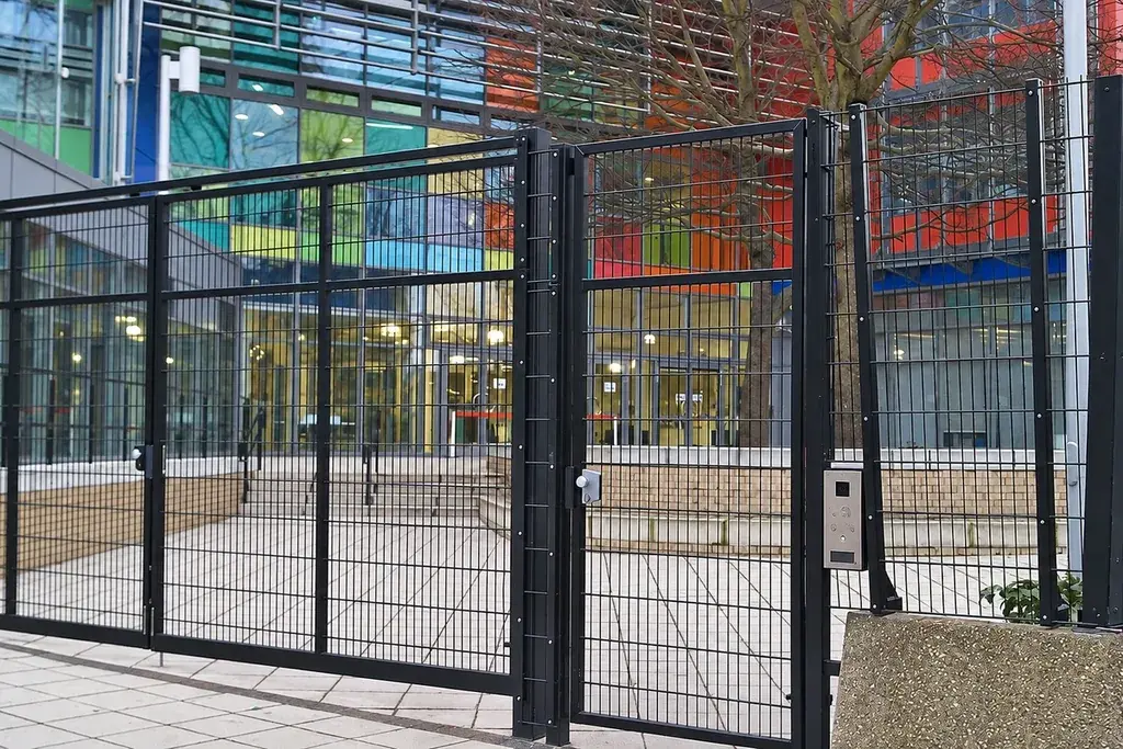
Distinguish the dimensions on a section and plan
| Field | Meaning | Where to show it |
|---|---|---|
| Clear passage width | Usable unobstructed opening in the defined operating position | Plan at the specified opening angle |
| Structural opening | Space between identified post faces or supporting structures | Plan with the measurement surfaces labelled |
| Leaf width | Overall manufactured leaf dimension | Fabrication elevation or leaf drawing |
| Clear height | Available overhead passage where restricted | Elevation through the opening |
| Ground clearance | Lower-edge gap above the defined finished surface | Elevation and movement path |
| Operating envelope | Space occupied during movement and at rest | Plan covering the full travel |
Gate hardware can occupy part of the structural opening. A drawing should make that reduction visible instead of letting the installer discover it after the posts are fixed.
Work through a single-leaf example
Assume a hypothetical opening with 1,200 mm between post faces. The approved arrangement reserves 35 mm at the hinge side and 25 mm at the latch side between those faces and the leaf edges. The resulting leaf width is 1,200 − 35 − 25 = 1,140 mm.
Now assume the leaf and hinge geometry project 50 mm into that structural opening in the specified fully open position. The usable passage is then 1,150 mm, not 1,200 mm and not 1,140 mm. These values describe one illustrative geometry; they are not recommended hinge gaps or a standard gate size.
For an actual order, have the gate designer draw the open position and dimension the remaining passage. On a double-leaf gate, distinguish the full opening from the opening available with only the active leaf in use. A maintenance leaf kept locked does not automatically contribute to everyday pedestrian access.
Check the ground throughout movement
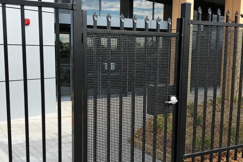
Measure the finished surface through the swing or sliding travel, including slopes, channels and thresholds. A gate that clears the ground when closed may bind partway through its movement. Raising the leaf to solve that problem changes the lower-edge gap and may affect containment or the boundary requirement.
A vehicle route may include a high point or crossfall that the plan view does not show. Carry these into the gate section before approving the leaf. See the sagging and binding diagnosis for the measurements that separate ground interference from movement in the post or frame.
Give the hardware a defined function
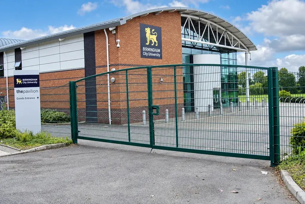
List hinges or running gear, latch, lock, drop bolts, stops and any retention devices. State which components are included in the gate supply and which are supplied by another party. Name the intended operation rather than specifying a familiar lock without checking how users will enter and leave.
For powered operation, create an interface schedule covering the drive, controls, protective measures, power, cabling and commissioning responsibilities. The automated-gate procurement guide addresses those interfaces. A manual leaf prepared for a motor is not a commissioned powered gate.
Close the schedule before fabrication
Review each gate against the adjacent fence: height, infill, post connections, finish and topping where applicable. Gate posts should be identified as gate supports, not counted as ordinary line posts unless the approved design explicitly allows it.
The release package should include the gate ID, dimensional drawing, opening direction, finished levels, hardware arrangement and revision. Keep left/right descriptions tied to a stated viewing direction. Finally, verify the supplied assembly and passage dimension after installation under the agreed handover procedure.
This sequence produces a gate schedule that can be quoted, built and checked without relying on an ambiguous nominal width. The gate collection identifies available construction families; the schedule defines the actual opening required.