
By FencingWise Editorial Team · Updated 17 September 2026.
Identify the support system first
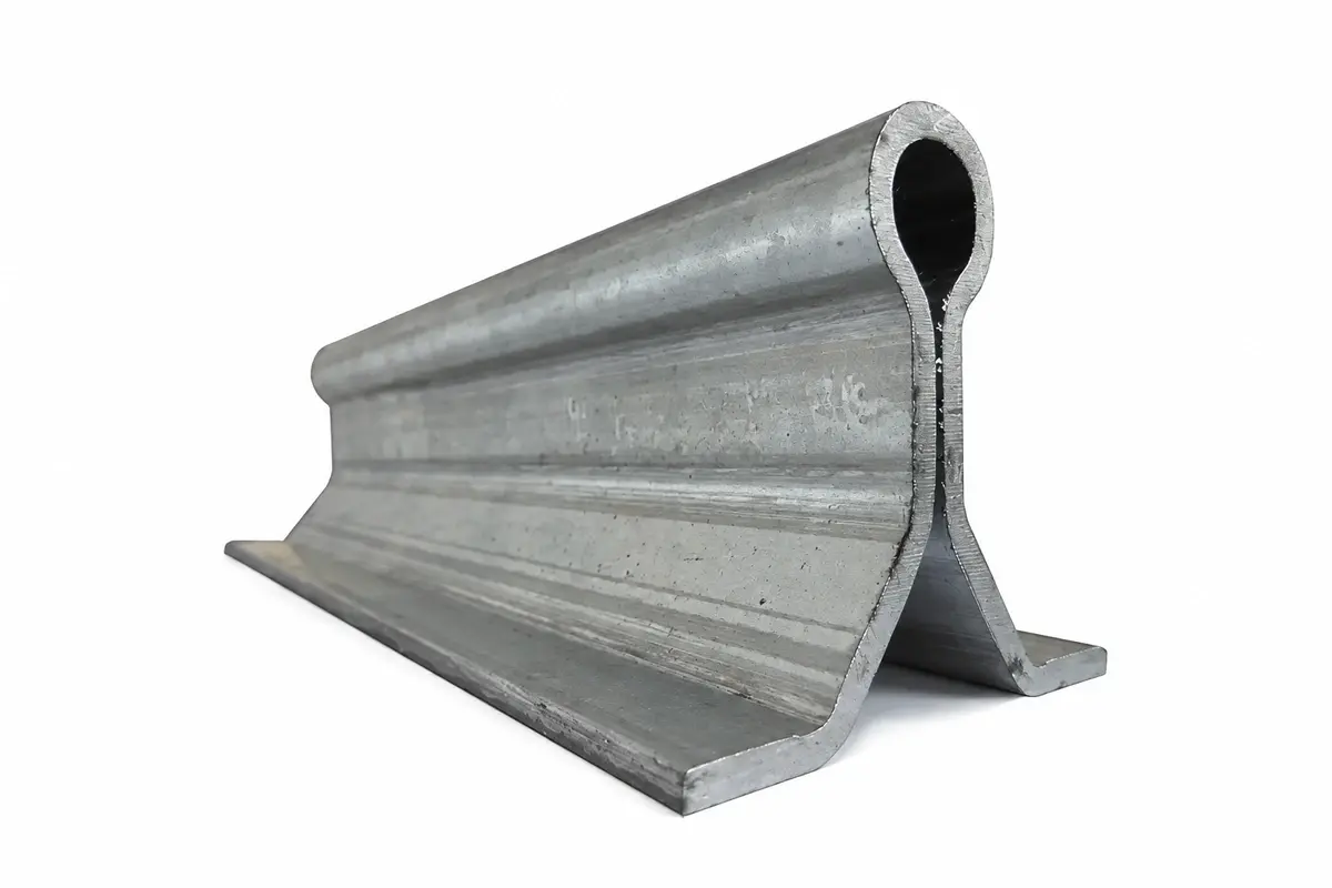
A tracked gate rolls on a rail across the entrance. A cantilever gate uses a supporting arrangement beside the opening and a leaf structure that spans it without a ground track through the passage.
Their parts lists differ. A tracked gate needs compatible wheel and rail profiles, rail support and drainage arrangements. A cantilever gate needs the selected beam, carriages, support spacing and counterbalance geometry. Do not combine components solely because their nominal sizes appear similar.
The tracked-versus-cantilever guide covers the initial system choice. Once that choice is made, schedule the hardware around the exact leaf and support arrangement.
Draw the parking space before pricing the leaf
For an illustrative tracked gate, assume a 6.0 m clear opening, 0.20 m closing overlap and 0.30 m rear extension. The resulting simplified leaf length is:
6.0 + 0.20 + 0.30 = 6.50 m.
If the layout also reserves 0.25 m beyond the parked leaf for the chosen end arrangement, the required straight parking length becomes 6.75 m.
These are layout assumptions, not a standard allowance. Actual travel, post locations and hardware projections must be drawn. A cantilever leaf may need a substantially different length determined by its selected support system; do not apply the tracked-gate calculation to it.
Mark utilities, walls, pedestrian routes and vehicle turning space within the parking area. An empty strip on a plan may not remain unobstructed during daily operations.
Assign every component to a mechanical function
| Function | Tracked arrangement | Cantilever arrangement |
|---|---|---|
| Carry vertical load | Wheels and supported rail | Carriages and compatible beam |
| Control lateral movement | Guide rollers or guides | Designed guidance and carriage system |
| Retain the leaf | Compatible anti-lift and derailment measures | Retention specified for the beam and supports |
| Limit travel | Mechanical end arrangements | Mechanical end arrangements |
| Receive the closed leaf | Receiver or catch where designed | Receiver or end support where designed |
| Drive movement | Manual operating provision or powered drive | Manual operating provision or powered drive |
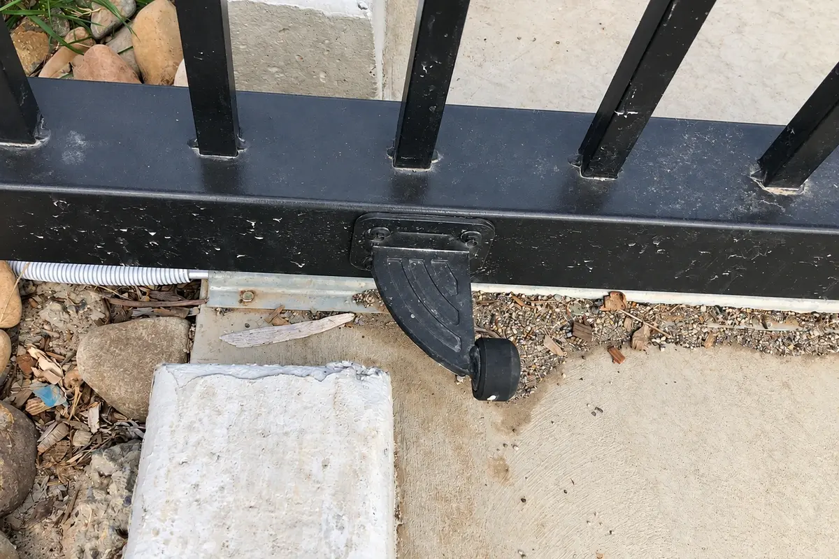
A controller's limit setting is not a substitute for every mechanical retention function. Likewise, a guide roller should not be assumed to carry loads outside its design role.
HSE's powered-gate guidance identifies derailment, falling, trapping and shear hazards among the issues that gate design must address. A component list should support that whole-system assessment.
Check compatibility beyond bolt-hole spacing
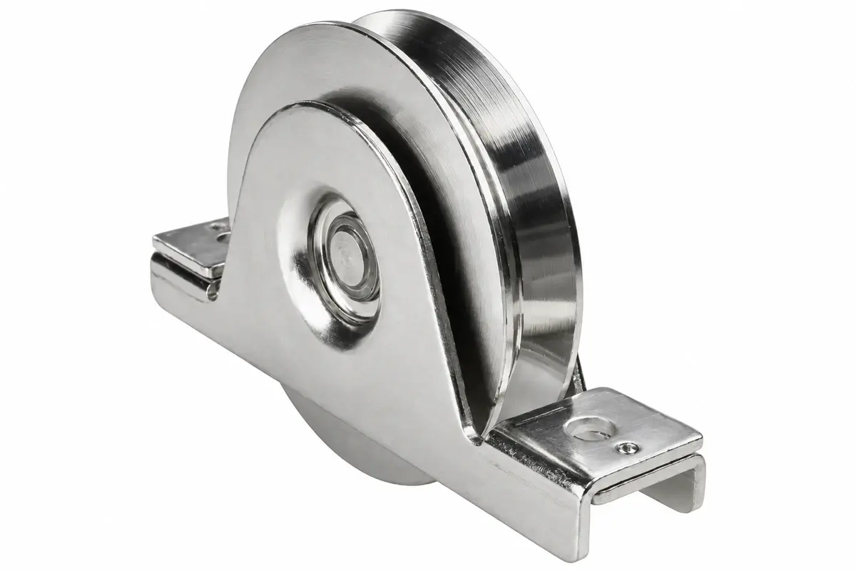
Compare the wheel groove with the rail profile, the carriage with the beam, and the guide roller with the available frame contact surface. The same overall diameter does not establish compatibility.
Record the complete leaf mass and its distribution. A heavy lock box, solid infill or equipment cabinet can change support reactions. Do not divide the weight equally between wheels or carriages unless the actual geometry and design justify that distribution.
For a simple static illustration, a 400 kg leaf has a weight of approximately 3,924 N using 9.81 m/s². Two supports do not automatically carry 1,962 N each: equal sharing requires the centre of gravity to be midway between those supports in the condition being assessed. Cantilever reactions can be particularly unequal as the leaf moves.
Inspect the track and operating corridor
For a tracked system, check rail continuity, alignment, fixings and drainage. Record joints and transitions where impact or debris may affect movement. A clear track at handover needs a maintenance method that keeps it clear later.
For either system, inspect the complete travel corridor with the leaf in closed, intermediate and open positions. Moving mesh passing a fixed post or adjacent fence can create a different hazard from the leading closing edge.
The equipment schedule should identify any guarding and sensing that protects those locations. Powered-gate assessment and commissioning require competent personnel; a smooth manual test alone does not establish safe powered operation.
Use commissioning records that can be repeated
Record the gate ID, hardware models, support dimensions, installed settings and relevant inspection results. Note where adjustments are made and which parts are not user-adjustable.
A useful mechanical check follows movement through the full permitted travel, observes support and guide engagement, verifies end retention and checks the closed receiver. Powered functions and protective devices then require their own specified tests.
If binding occurs, stop and locate the cause. Increasing drive force can conceal rail misalignment or a damaged support while making the consequences worse. Use the binding diagnosis to separate geometry, support and surface problems before parts are replaced.